Yamaha 01V96 Owner's Manual
Yamaha 01V96 Manual
 |
View all Yamaha 01V96 manuals
Add to My Manuals
Save this manual to your list of manuals |
Yamaha 01V96 manual content summary:
- Yamaha 01V96 | Owner's Manual - Page 1
Owner's Manual Keep This Manual For Future Reference. E - Yamaha 01V96 | Owner's Manual - Page 2
be used. Follow all installation instructions. Failure to follow instructions could void your FCC authorization to use this product in the USA. 3. NOTE: This product has been tested and found to comply with the requirements listed in FCC Regulations, Part 15 for Class "B" digital devices. Compliance - Yamaha 01V96 | Owner's Manual - Page 3
RISK OF ELECTRIC SHOCK DO NOT OPEN CAUTION: TO REDUCE THE RISK OF ELECTRIC SHOCK, DO NOT REMOVE COVER (OR BACK). NO USER-SERVICEABLE PARTS INSIDE. REFER SERVICING TO QUALIFIED SERVICE PERSONNEL. The above warning is located on the rear of the unit • Explanation of Graphical Symbols The lightning - Yamaha 01V96 | Owner's Manual - Page 4
cord for this unit. Using other types may be a fire and electrical shock hazard. • This unit has a slot for installing mini-YGDAI cards. For technical reasons, certain card combinations are not supported. Before installing any cards, check the Yamaha web site to if your card is compatible. Installing - Yamaha 01V96 | Owner's Manual - Page 5
while it's covered with a cloth or dust sheet. • This unit is equipped with a dedicated ground connection to prevent electrical shock. Before connecting the power Before replacing the batteries, back up your data to a memory card, or another unit by using MIDI Bulk Dump. • The digital circuits of - Yamaha 01V96 | Owner's Manual - Page 6
is available on the Yamaha Professional Audio Web site at: . Package Contents • 01V96 Digital Mixing Console • CD-ROM • Power cord • This manual • Studio Manager Installation Guide Optional Extras • RK1 Rack Mount Kit • mini YGDAI I/O cards 01V96-Owner's Manual - Yamaha 01V96 | Owner's Manual - Page 7
About this Owner's Manual vii About this Owner's Manual This Owner's Manual explains how to operate the 01V96 Digital Mixing Console. The Table of Contents can help you to familiarize yourself with the manual's organization and to locate tasks and topics. The index can help you locate specific - Yamaha 01V96 | Owner's Manual - Page 8
Tutorial 47 Connections and Setup 47 Initial Track Recording 49 Overdubbing to Other Tracks 60 Mixing Recorded Tracks into Stereo (Mixdown 63 6 Analog I/O & Digital I/O 69 Analog Inputs & Outputs 69 Digital Inputs & Outputs 71 Converting Sampling Rates of Signals Received at I/O Card Inputs - Yamaha 01V96 | Owner's Manual - Page 9
Libraries 171 About the Libraries 171 General Library Operation 171 Using Libraries 173 17 Remote Control 185 About Remote Function 185 Pro Tools Remote Layer 186 Nuendo Remote Layer 202 Other DAW Remote Layers 202 MIDI Remote Layer 203 Machine Control Function 208 01V96-Owner's Manual - Yamaha 01V96 | Owner's Manual - Page 10
289 Digital Input Spec 290 Digital Output Spec 290 I/O SLOT Spec 290 CONTROL I/O Spec 291 Dimensions 291 Appendix C: MIDI 292 Scene Memory to Program Change Table 292 Initial Parameter to Control Change Table 293 MIDI Data Format 309 Appendix D: Options 323 Index 324 01V96-Owner's Manual - Yamaha 01V96 | Owner's Manual - Page 11
audio system features remote control function for DAWs (Digital Audio Workstations) as popularized by the DM2000 and 02R96 Digital Mixing Consoles. The 01V96 offers the following features: ■ Hardware Features • 100-mm motorized faders x 17 • Faders can set levels for Input Channels, Aux send levels - Yamaha 01V96 | Owner's Manual - Page 12
to suit connected devices. ■ Remote Control • Control and manage your 01V96 from your Mac or PC using bundled Studio Manager software. • Remote Layer for remote control of Pro Tools, Nuendo, and other DAWs that support the Pro Tools protocol • Control an external recorder via MMC commands. ■ MIDI - Yamaha 01V96 | Owner's Manual - Page 13
(p. 17) LAYER Section (p. 19) SCENE DIO/SETUP MIDI UTILITY / INSERT/ PAN/ PAIR/ DELAY ROUTING GROUP PATCH DYNAMICS EQ EFFECT FADER MODE VIEW AUX 1 AUX 2 AUX 3 AUX 4 AUX 5 AUX 6 AUX 7 AUX 8 HOME (METER) LAYER 1-16 17-32 MASTER REMOTE Display Section (p. 19) OVER 0 -3 -6 -9 -12 -15 - Yamaha 01V96 | Owner's Manual - Page 14
an external effects processor to AD input channels. 1/4" phone plug Tip (send) Tip (send) Ring (return) 1/4" phone plug Sleeve (ground) Connect to INSERT jack To processor's input 1/4" phone plug Sleeve (ground) Tip (return) Sleeve (ground) From processor's output 01V96-Owner's Manual - Yamaha 01V96 | Owner's Manual - Page 15
control sets the level of the PHONES. (See page 131 for more information on monitoring through the headphones.) E PHONES jack You can connect a set of stereo headphones to this stereo phone jack. The signals output from the MONITOR OUT connectors are also output from this jack. 01V96-Owner's Manual - Yamaha 01V96 | Owner's Manual - Page 16
50 40 60 70 50 1 17 AUX 1 STEREO Section 1 SEL 2 ON A [SEL] button Selects the Stereo Out. B [ON] button Turns the Stereo Out on or off. C [STEREO] fader This 100mm motorized fader adjusts the final output level of the Stereo Out. 0 5 10 15 20 30 40 50 60 70 3 STEREO 01V96-Owner's Manual - Yamaha 01V96 | Owner's Manual - Page 17
You can now adjust the send level of signals routed from Input Channels to the corresponding Aux buses by using the faders. B [HOME] button This button recalls Meter pages that display Input Channel levels or Output Channel (Bus Out, Aux Out, Stereo Out) levels (see page 34). 01V96-Owner's Manual - Yamaha 01V96 | Owner's Manual - Page 18
to set up the 01V96, including digital input and output setup and remote control setup (see pgaes 72, 188). C [MIDI] button This button displays a MIDI page, enabling you to make MIDI settings (see page 215). D [UTILITY] button This button displays a Utility page, enabling you to use the internal - Yamaha 01V96 | Owner's Manual - Page 19
. You can use this layer to control Bus Outs and AUX Sends. (See page 31 for more information on the Master layer.) C [REMOTE] button This button selects the Remote Layer as the layer controlled in the Channel Strip section. You can use this layer to control external MIDI devices or computer-based - Yamaha 01V96 | Owner's Manual - Page 20
button indicator of the currently-selected band lights up. F [Q] control This control adjusts the currently-selected band Q. G [FREQUENCY] control This control adjusts the currently-selected band frequency. H [GAIN] control This control adjusts the currently-selected band gain. 01V96-Owner's Manual - Yamaha 01V96 | Owner's Manual - Page 21
SCENE MEMORY STORE 1 2 RECALL 3 2 Control Surface & Rear Panel A [STORE] button This button enables you to store the current mix settings. (See page 161 for more information 7 8 A [1]-[8] buttons You can assign any of the 167 functions to these User Defined buttons. 01V96-Owner's Manual - Yamaha 01V96 | Owner's Manual - Page 22
Panel Data Entry Section 3 DEC INC 4 1 2 ENTER A Parameter wheel This control adjusts the parameter values shown on the display. Turning it clockwise increases the value single or multiple channels are soloed. B [CLEAR] button This button "unsolos" all soloed Channels. 01V96-Owner's Manual - Yamaha 01V96 | Owner's Manual - Page 23
Rear Panel 23 Digital I/O Section MIDI/Control Section (p. 24) (p. 25) 2 Control Surface & Rear inputs. When the switches are on, +48V phantom power is supplied to the INPUT using the Monitor Source selector. 1/4" TRS phone plug Tip (hot) Ring (cold) Sleeve (ground) 01V96-Owner's Manual - Yamaha 01V96 | Owner's Manual - Page 24
connected external device to the 01V96. C ADAT IN/OUT connectors These optical TOSLINK connectors input and output ADAT digital audio signals. D 2TR OUT DIGITAL COAXIAL This RCA phono connector outputs consumer format (IEC-60958) digital audio. The connector is typically used to connect the digital - Yamaha 01V96 | Owner's Manual - Page 25
MIDI/Control Section Rear Panel 25 2 Control Surface & Rear Panel 1 2 A MIDI IN/THRU/OUT ports These standard MIDI IN, OUT and THRU ports enable you to connect the 01V96 to other MIDI equipment. B TO HOST USB port This USB port enables you to connect a computer equipped with a USB port. SLOT - Yamaha 01V96 | Owner's Manual - Page 26
below to install an optional mini-YGDAI card. 1 Make sure that the power to the 01V96 is turned off. 2 Undo the two fixing screws and remove the slot cover, as shown below. Keep the cover and fixing screws in a safe place for future use. 3 Insert the card between the guide rails and slide it all the - Yamaha 01V96 | Owner's Manual - Page 27
. E MIDI indicator This indicator appears when the 01V96 is receiving MIDI data via the MIDI IN port, USB port, or an installed MY8-mLAN card. F Surround mode indicator This indicator identifies the currently-selected Surround mode (ST=stereo, 3-1, 5.1, or 6.1) (see page 135). 01V96-Owner's Manual - Yamaha 01V96 | Owner's Manual - Page 28
This indicator identifies the 01V96's current sampling rate: 44.1 kHz (44k), 48 kHz (48k), 88.2 kHz (88k), or 96 kHz (96k). H ST IN channel levels These level controls indicate the level of ST IN the first page in the group: Double-click the button you selected in Step 1. 01V96-Owner's Manual - Yamaha 01V96 | Owner's Manual - Page 29
use the display interface. Operating Basics Rotary Controls & Faders The rotary controls and faders enable you to adjust the continuously variable parameter values, including Input Channel levels and effects parameters while the edited value is flashing, the edit is cancelled. 01V96-Owner's Manual - Yamaha 01V96 | Owner's Manual - Page 30
uppercase characters and various punctuation marks. The figure on the right shows lowercase characters and numbers. Use the cursor buttons to select characters, and press the [ENTER] button to enter them into the entry, move the cursor to the CANCEL button, then press [ENTER]. 01V96-Owner's Manual - Yamaha 01V96 | Owner's Manual - Page 31
Layer 1-16 Input Channel Layer 17-32 Master Layer Remote Layer The currently-selected layer determines the function of the channel strip, [SEL] buttons, [SOLO] buttons, [ON] buttons, and faders. Use the LAYER buttons to select a layer you wish to edit using the channel strip controls. LAYER 1-16 - Yamaha 01V96 | Owner's Manual - Page 32
01V96, press the corresponding [SEL] button. To adjust the Pan and EQ settings, use the rotary controls in the SELECTED CHANNEL section. To select a channel on pages that cover FREQUENCY LOW-MID GAIN LOW Tip: For paired Input or Output Channels, the channel for which you 01V96-Owner's Manual - Yamaha 01V96 | Owner's Manual - Page 33
indicators identify the following Fader modes: AUX 1 AUX 2 AUX 3 AUX 4 3 Operating Basics • When the [HOME] button indicator lights up: You can use channel faders to control Input Channels and ST IN Channel levels or Output Channels (Aux AUX 5 AUX 6 AUX 7 AUX 8 Out 1-8, Bus Out 1-8) master - Yamaha 01V96 | Owner's Manual - Page 34
FADER Immediately before the fader. • POST FADER Immediately after the fader. 3 Press the FADER MODE [HOME] button repeatedly until the page listed below that contains the desired channels appears. - CH1-32 page This page displays the Input Channel 1-32 levels respectively. 01V96-Owner's Manual - Yamaha 01V96 | Owner's Manual - Page 35
ST IN Channel 1-4 levels separately. 3 Operating Basics - Master page This section displays the Output Channel (Aux Out 1-8, Bus Out 1-8, Stereo Out) levels altogether. - Effect page This page displays the internal effects processor 1-4 input and output levels altogether. 01V96-Owner's Manual - Yamaha 01V96 | Owner's Manual - Page 36
gain reduction for the compressor • LEVEL Input Channel input level, or Output Channel output level Tip: These pages also allow you to change the metering position using the POSITION parameter. This parameter setting the Peak Hold function, turn the PEAK HOLD button off. 01V96-Owner's Manual - Yamaha 01V96 | Owner's Manual - Page 37
PHONES DISPLAY ACCESS SCENE MEMORY SCENE DIO/SETUP MIDI UTILITY / INSERT/ PAN/ PAIR/ DELAY ROUTING GROUP PATCH DYNAMICS EQ EFFECT FADER MODE VIEW AUX 1 AUX 2 AUX 3 AUX 4 AUX 5 AUX 6 AUX 7 AUX 8 HOME (METER) LAYER 1-16 17-32 MASTER REMOTE OVER 0 -3 -6 -9 -12 -15 -18 -24 -30 -36 - Yamaha 01V96 | Owner's Manual - Page 38
Real-time External Control Surface Modular Synthesis Plug-in System SCENE DIO/SETUP MIDI UTILITY / INSERT/ PAN/ PAIR/ DELAY ROUTING GROUP PATCH DYNAMICS EQ EFFECT FADER MODE VIEW AUX 1 AUX 2 AUX 3 AUX 4 AUX 5 AUX 6 AUX 7 AUX 8 HOME (METER) LAYER 1-16 17-32 MASTER REMOTE OVER - Yamaha 01V96 | Owner's Manual - Page 39
a computer-based DAW (Digital Audio Workstation). The 01V96 can provide audio input and output for the DAW. If you connect the 01V96 and the computer via USB, the 01V96's Remote function enables you to control the DAW's locate and transport functions and change the parameters. 01V96-Owner's Manual - Yamaha 01V96 | Owner's Manual - Page 40
to the wordclock master. If you are digitally connecting the 01V96 to other equipment, you must decide which device to use as the wordclock master and which devices to use as slaves, then set up all the devices accordingly. The 01V96 can be used as the wordclock master running at either 44 - Yamaha 01V96 | Owner's Manual - Page 41
PHONES DISPLAY ACCESS SCENE MEMORY SCENE DIO/SETUP MIDI UTILITY / INSERT/ PAN/ PAIR/ DELAY ROUTING GROUP PATCH DYNAMICS EQ EFFECT FADER MODE VIEW AUX 1 AUX 2 AUX 3 AUX 4 AUX 5 AUX 6 AUX 7 AUX 8 HOME (METER) LAYER 1-16 17-32 MASTER REMOTE OVER 0 -3 -6 -9 -12 -15 -18 -24 -30 -36 - Yamaha 01V96 | Owner's Manual - Page 42
Chapter 4-Connections and Setup The source select button indicators are explained below: A usable wordclock signal is present at this input, and it is in sync with the current 01V96 internal clock. No wordclock signal is present at this input. A usable wordclock signal is present at this input, but - Yamaha 01V96 | Owner's Manual - Page 43
By default, the Input Channels are patched as follows: • INPUT connectors 1-16 Input Channels 1-16 • ADAT IN channels 1-8 Input Channels 17-24 • Slot channels 1-8 Input Channels 25-32 • Outputs 1-2 of Internal Effects Processor 1-4 ST IN Channels 1-4 Connections and Setup Follow the steps - Yamaha 01V96 | Owner's Manual - Page 44
44 Chapter 4-Connections and Setup 3 Press [ENTER] to confirm the change. Tip: To restore the default patching, recall Input Patch memory #00 (see page 174). Patching Omni Outs By default, the output connectors are patched as follows: • OMNI OUT connectors 1-4 Aux Out 1-4 • ADAT OUT channels 1-8 - Yamaha 01V96 | Owner's Manual - Page 45
Input and Output Patching 45 2 Use the cursor buttons to move the cursor to a patch parameter (1) you wish to change, and rotate the Parameter ] to confirm the change. Tip: To restore the default patching, recall Output Patch memory #00 (see page 175). 4 Connections and Setup 01V96-Owner's Manual - Yamaha 01V96 | Owner's Manual - Page 46
46 Chapter 4-Connections and Setup 01V96-Owner's Manual - Yamaha 01V96 | Owner's Manual - Page 47
PHONES DISPLAY ACCESS SCENE MEMORY SCENE DIO/SETUP MIDI UTILITY / INSERT/ PAN/ PAIR/ DELAY ROUTING GROUP PATCH DYNAMICS EQ EFFECT FADER MODE VIEW AUX 1 AUX 2 AUX 3 AUX 4 AUX 5 AUX 6 AUX 7 AUX 8 HOME (METER) LAYER 1-16 17-32 MASTER REMOTE OVER 0 -3 -6 -9 -12 -15 -18 -24 -30 -36 - Yamaha 01V96 | Owner's Manual - Page 48
this case, you must set the hard disk recorder so that it will synchronize to an external clock. • If the 01V96 and a connected device are not synching to each other, the 01V96 displays the message "Sync Error!" If this happens, check the ADAT IN and OUT connections, digital I/O card connection, and - Yamaha 01V96 | Owner's Manual - Page 49
as shown below. 5 Tutorial By default (as shown in this example), the signals output from Bus Outs 1-8 are routed to the ADAT OUT connector (Tracks point for mixing and recording. They display channel input and output levels, and compressor and gate gain reduction amounts. 01V96-Owner's Manual - Yamaha 01V96 | Owner's Manual - Page 50
[GAIN] controls. Pairing Channels On the 01V96, you can pair adjacent odd-even channels for stereo operation. Faders and most mix parameters of paired channels (excluding the Input Patch, phase, routing, and pan parameters) are linked. Pairing Input Channels is useful when you are connecting stereo - Yamaha 01V96 | Owner's Manual - Page 51
applied to the fader motor, causing malfunction. Routing Signals To record the 01V96 input signals to an external digital multitrack recorder, you must specify the destination of the signals for each Input Channel. This process is called "routing." There are two routing methods. • Using Bus Outs - Yamaha 01V96 | Owner's Manual - Page 52
Chapter 5-Tutorial • Using Direct Outs Each Input Channel signal is directly routed to and output from the specified output connectors and channels. Use this method to patch each Input Channel directly to each MTR track. The following example illustrates the signals directly output from ADAT OUT - Yamaha 01V96 | Owner's Manual - Page 53
Stereo Bus. Tip: The S buttons for paired channels are linked. 5 Tutorial 3 To route Input Channel signals to the connected digital MTR via Buses 1-8, use the 1-8 buttons to specify a Bus Out as the destination for each of the Input Channels to which the musical instruments and microphone are - Yamaha 01V96 | Owner's Manual - Page 54
tracks. (Refer to the owner's manual for the digital MTR for more information.) In this way, signals sent to Tracks 1-8 of the digital MTR are returned to the 01V96's Input Channels 17-24. 2 Press the LAYER [17-32] button. Input Channel Layer 17-32 is now available for control from the channel strip - Yamaha 01V96 | Owner's Manual - Page 55
control, and [PHONES] control to set the appropriate monitoring level. Now you can monitor via the monitoring system and headphones the signals sent from Input Channels 17-24 to the Stereo Bus. Note: If the L & R level meters reach the "OVER" position, lower the [STEREO] fader. 01V96-Owner's Manual - Yamaha 01V96 | Owner's Manual - Page 56
Tutorial EQ'ing the Input Signals The 01V96's Input Channels feature 4-band full parametric EQ. This section describes how to apply EQ to the signals before they are recorded to the tracks. 1 Press the LAYER [1-16] button. Input Channel Layer 1-16 is now available for control . 01V96-Owner's Manual - Yamaha 01V96 | Owner's Manual - Page 57
how to compress the signals before they are recorded to the tracks. 1 Press the LAYER [1-16] button. Input Channel Layer 1-16 is now available for control from the channel strip section. 2 Press the [SEL] button of the Input Channel to which you want to apply compression. 01V96-Owner's Manual - Yamaha 01V96 | Owner's Manual - Page 58
the RECALL button located to the left of the library title list, then press [ENTER]. The selected program is recalled. 6 Press the [F3] button. The 01V96 displays the Dynamics | Comp Edit page, which enables you to adjust compressor parameters. 01V96-Owner's Manual - Yamaha 01V96 | Owner's Manual - Page 59
Input Channel levels and Bus 1-8 output levels are not clipping. 2 When you finish playing, stop the digital MTR. 3 To check the recording, play the digital MTR from the beginning. 4 If you are satisfied with the recording, stop the playback and disarm Tracks 1-8 on the recorder. 01V96-Owner's Manual - Yamaha 01V96 | Owner's Manual - Page 60
which the instruments or microphone are connected are lit, then raise the corresponding faders to 0dB. Turn off the [ON] buttons for the channels not in use. 5 While the musicians play the musical instruments, check the input channel levels using the level meters on the display. 01V96-Owner's Manual - Yamaha 01V96 | Owner's Manual - Page 61
of the digital MTR back to the 01V96's Input Channels 25 and 26) through the MONITOR OUT connectors and the PHONES jack. 1 Arm the connected digital MTR's owner's manual for the digital MTR for more information.) 2 Press the LAYER [17-32] button. Input Channel Layer 17-32 is now available for control - Yamaha 01V96 | Owner's Manual - Page 62
that the Input Channel levels are not clipping. 2 When the musicians finish playing, stop the digital MTR. 3 To check the recording, play the digital MTR from the beginning. 4 If you are satisfied with the recording, stop the playback and disarm Tracks 9 and 10 on the recorder. 01V96-Owner's Manual - Yamaha 01V96 | Owner's Manual - Page 63
PHONES DISPLAY ACCESS SCENE MEMORY SCENE DIO/SETUP MIDI UTILITY / INSERT/ PAN/ PAIR/ DELAY ROUTING GROUP PATCH DYNAMICS EQ EFFECT FADER MODE VIEW AUX 1 AUX 2 AUX 3 AUX 4 AUX 5 AUX 6 AUX 7 AUX 8 HOME (METER) LAYER 1-16 17-32 MASTER REMOTE OVER 0 -3 -6 -9 -12 -15 -18 -24 -30 -36 - Yamaha 01V96 | Owner's Manual - Page 64
R." The signals input at the 2TR IN DIGITAL connector are now routed to ST IN Channel 2 L and R. 5 Use the ST IN [ST IN] button to select ST IN Channels 1 and 2. The ST IN [ST IN] button selects an ST IN channel pair (ST IN Channels 1 and 2 or 3 and 4) which you can control using the buttons - Yamaha 01V96 | Owner's Manual - Page 65
Tutorial 5 Input Channel 17-32 signals input from Tracks 1-16 of the digital MTR are now routed through the Stereo Bus, to the STEREO OUT and 2TR OUT DIGITAL connectors. 5 Use the PAN parameter controls for Input to display the Gate Edit page, then edit the gate parameters. 01V96-Owner's Manual - Yamaha 01V96 | Owner's Manual - Page 66
66 Chapter 5-Tutorial Using the Internal Effects The 01V96 features four internal multi-effects processors that can be used via Aux Sends and Returns or by inserting them into specific channels. This section describes how to use internal Effects processor 1 via Aux Send 1, and apply reverb to the - Yamaha 01V96 | Owner's Manual - Page 67
level of the signals routed from Input Channels to Effects processor 1. 9 To adjust the effect return level, use the rotary level control located on the left side of the ST IN section on the top panel. You can view the current level in the upper-right corner of the display. 01V96-Owner's Manual - Yamaha 01V96 | Owner's Manual - Page 68
DIO/Setup | Word Clock page and select "2TRD" (2TR IN DIGITAL) as the wordclock source. When the master recorder finishes playing back, turn off the [ON] button for ST IN Channel 2. Tip: If you desire, you can store the current mix settings to memory as a Scene (see page 161). 01V96-Owner's Manual - Yamaha 01V96 | Owner's Manual - Page 69
and direct boxes. The phantom [+48V] switches on the rear panel turn on or off the +48V phantom power feed to the corresponding inputs. Inputs 1 through 12 feature pad switches, which attenuate input signals by 20 dB. These switches are effective on both INPUT A and B signals. 01V96-Owner's Manual - Yamaha 01V96 | Owner's Manual - Page 70
you to connect a monitoring system, master recorder, effects processors and other line-level devices. • MONITOR OUT connectors L/R These balanced TRS-type phone connectors output monitoring signals or input signals routed from the 2TR IN connectors. The nominal output level is +4 dB. Use the Monitor - Yamaha 01V96 | Owner's Manual - Page 71
71 Digital Inputs & Outputs The 01V96 rear panel features digital input and output connectors that enable you to connect external digital devices. Any signal path can be patched to these digital inputs and outputs. You can also add analog and digital I/Os by installing an optional I/O card in - Yamaha 01V96 | Owner's Manual - Page 72
I/O Card Inputs An optional MY8-AE96S Digital I/O card features sampling rate converters, so you can easily convert the sampling frequency of digital inputs to the current 01V96 sampling rate. 1 Press the DISPLAY ACCESS [DIO/SETUP] button repeatedly until the DIO/Setup | Format page appears. Use the - Yamaha 01V96 | Owner's Manual - Page 73
-Consumer) format. This parameter can display the following values: Parameter value General Laser Optical D/D Conv Magnetic Description Temporarily used Laser optical device Digital - Digital converter and signal processing device Magnetic tape device and magnetic disk device 01V96-Owner's Manual - Yamaha 01V96 | Owner's Manual - Page 74
or channels that are set to "OFF." • Dithering is effective only when the resolution of the receiving device is lower than that of the 01V96. Tip: To copy the currently-selected setting to all channels, double-click the [ENTER] button. The copy confirmation window is displayed. 01V96-Owner's Manual - Yamaha 01V96 | Owner's Manual - Page 75
high sampling rate (i.e., 88.2 kHz or 96 kHz). Select this mode if the devices that support the higher sampling rates transmit or receive data. Note: This mode is available only for the slot in which the optional Yamaha MY8-AE96 or MY8-AE96S Digital I/O card is installed. 01V96-Owner's Manual - Yamaha 01V96 | Owner's Manual - Page 76
sampling rate of the 01V96. For example, this is useful when you wish to send 44.1 kHz digital signals from an external HDR to the 01V96 running at 88.2 kHz. Note: • This mode is unavailable for the slot in which the optional Yamaha MY9-AE96 or MY8-AE96S Digital I/O card is installed. • You cannot - Yamaha 01V96 | Owner's Manual - Page 77
BAND EQ (4-band equalizer) This parametric EQ features four bands (high, high-mid, low-mid, and low). • INPUT DELAY (Input delay) This section enables you to delay input signals. You can use this delay to fine-tune the timing between channels, or as a delay effect with feedback. 01V96-Owner's Manual - Yamaha 01V96 | Owner's Manual - Page 78
be routed to Aux Sends from either the pre-fader or post-fader position. • INSERT This section enables you to patch input signals to external devices via the on-board I/O connectors or I/O card, or insert the internal effect processors. You can patch any inputs, outputs, or I/O card channels. (Note - Yamaha 01V96 | Owner's Manual - Page 79
the phase separately for each of the ST IN Channels or for each channel in a channel pair. If you selected the desired ST IN Channel using the corresponding [SEL] button, pressing the same [SEL] button repeatedly will toggle between channels L and R. 01V96-Owner's Manual - Yamaha 01V96 | Owner's Manual - Page 80
time can be set using units of meters, feet, samples, beats, or frames, which you select by using the DELAY SCALE buttons. • MIX This parameter sets the mix balance of dry (Input Channel) and wet (delayed) signals. • FB.GAIN This parameter sets the amount of delay feedback. 01V96-Owner's Manual - Yamaha 01V96 | Owner's Manual - Page 81
that synchronizes to the song tempo. Gating Input Channels To set the Input Channel gates, use the [SEL] buttons to select the desired Input Channel, then press the DISPLAY ACCESS [DYNAMICS the gate type, recall a program that uses the desired gate type from the Gate library. 01V96-Owner's Manual - Yamaha 01V96 | Owner's Manual - Page 82
the compressor type used by the currently-selected channel's compressor (COMP/EXPAND/COMP (H)/COMP (S)). Note: You cannot change the Compressor type on this page. To change the compressor type, recall a program that uses the desired compressor type from the compressor library. 01V96-Owner's Manual - Yamaha 01V96 | Owner's Manual - Page 83
the cursor to the knob for the desired Input Channel, then rotate the Parameter wheel to set the amount of attenuation in the range of -96 dB to +12 dB. Tip: You can also set the attenuation amount (in dB) for the currently-selected channel on the EQ | EQ Edit page. 01V96-Owner's Manual - Yamaha 01V96 | Owner's Manual - Page 84
Selects the type of EQ. TYPE I is the EQ type used on legacy Yamaha 02R series digital mixing consoles. TYPE II is a newly developed algorithm. C ATT Determines the 1. The LOW and HIGH GAIN controls function as filter on/off controls when Q is set to HPF or LPF respectively. 01V96-Owner's Manual - Yamaha 01V96 | Owner's Manual - Page 85
Input Channel pan controls operate independently. • GANG In Gang mode, paired Input Channel pan controls operate in unison, maintaining the current pan range. • INV GANG In Inverse Gang mode, paired Input Channel pan controls operate in unison but move in opposite directions. 01V96-Owner's Manual - Yamaha 01V96 | Owner's Manual - Page 86
Rs C Bs E 8 L=Left, R=Right, C=Center, S=Surround, Ls=Left Surround Rs=Right Surround, E=Low Frequency Effect, Bs=Back Surround The above table shows the default assignment. The actual assignment may vary, depending on the settings on the DIO/Setup | Surround Bus Setup page. 01V96-Owner's Manual - Yamaha 01V96 | Owner's Manual - Page 87
the currently-selected Input Channel on the View | Parameter or Fader pages. ■ Viewing the Gate, Compressor, and EQ Settings To display the View | Parameter page for a specific Input Channel, use the corresponding [ off and set the parameters. (See page 81 for more information.) 01V96-Owner's Manual - Yamaha 01V96 | Owner's Manual - Page 88
Pan, Fader, and Aux Send Level Settings To display the View | Fader page of a certain Input Channel, use the Fader section • PAN control This control adjusts the currently-selected Input Channel's Pan parameter. Press the [ENTER] button to reset the Pan control to Center. 01V96-Owner's Manual - Yamaha 01V96 | Owner's Manual - Page 89
/COMP These buttons indicate which Fader, Mute, EQ, or Comp group, if any, the currently-selected Input Channel is in. If the channel is in a group, the group number appears. If the channel is not in a group, "-" appears. (The compressor is unavailable for the ST IN Channels.) 01V96-Owner's Manual - Yamaha 01V96 | Owner's Manual - Page 90
input level and/or pan settings. 3 Use the faders to set the Input Channel levels. 4 Rotate the SELECTED CHANNEL [PAN] control to adjust the pan settings. When you rotate the [PAN] control channel currently being controlled is indicated in the upper-left corner of the display.) 01V96-Owner's Manual - Yamaha 01V96 | Owner's Manual - Page 91
Use the SELECTED CHANNEL [Q], [FREQUENCY], and [GAIN] controls to adjust the Q, frequency, and gain of the band selected in Step 2. When the Auto EQUALIZER Display (page 227) check box is on, the 01V96 displays the EQ/EQ Edit page. 7 Input Q, frequency and gain for each band. 01V96-Owner's Manual - Yamaha 01V96 | Owner's Manual - Page 92
control) are listed below: Linked parameters [SEL] buttons Faders Channel on/off Insert on/off Solo on/off Solo Safe Aux on/off Aux Send level Aux an ST IN channel 1-4 with an Input Channel. To pair channels, or to cancel channel pairs, you can use the [SEL] buttons on the top 01V96-Owner's Manual - Yamaha 01V96 | Owner's Manual - Page 93
pair. Input Channels ■ Pairing Input Channels Using the Display 1 Press the [PAIR/GROUP] button repeatedly until the Pair/Grup | Input page appears fader (e.g., CH1 & CH17, CH16 & CH32, etc.). This mode is useful when you wish to use one fader to control both stereo channels. 01V96-Owner's Manual - Yamaha 01V96 | Owner's Manual - Page 94
example, it may be helpful for mixdown if you name a particular Input Channel with the type of musical instrument connected to the corresponding input jack. 1 Press the DISPLAY ACCESS [PATCH] button repeatedly until the the cursor to the INITIALIZE button, then pressing [ENTER]. 01V96-Owner's Manual - Yamaha 01V96 | Owner's Manual - Page 95
window appears, enabling you to enter a name. 3 Edit the name, move the cursor to the OK button, then press [ENTER]. The new name is now effective. Tip: The edited name is stored in the Input Patch library. 7 Input Channels 01V96-Owner's Manual - Yamaha 01V96 | Owner's Manual - Page 96
96 Chapter 7-Input Channels 01V96-Owner's Manual - Yamaha 01V96 | Owner's Manual - Page 97
enables you to route the Stereo Out signals to external devices via the on-board connectors or I/O card, or insert internal effects processors. • ATT (Attenuator) This section enables you to attenuate or amplify the level of signals to be input to the EQ. The attenuator prevents post-EQ signals from - Yamaha 01V96 | Owner's Manual - Page 98
card by using the Patch | Out Patch pages. Bus Out 1-8 The Bus Out 1-8 section mixes signals routed from Input Channels to the specified buses, processes them using on-board page 105). • By default, Slot channels 1-8 and 9-16 and ADAT OUT channels 1-8 are patched to the Bus Out 1-8 outputs. However, - Yamaha 01V96 | Owner's Manual - Page 99
) are the same as for Input Channels, except that this page does not include the MIX/FB.GAIN parameters (see page 80). Tip: You can also display the Out Dly page by pressing the [ /INSERT/DELAY] button once, then press the [SEL] button to select the Stereo Out or Bus Out 1-8. 01V96-Owner's Manual - Yamaha 01V96 | Owner's Manual - Page 100
Edit page, and use the [SEL] use the [SEL] buttons to select the Stereo Out or Bus Out 1-8. The parameters on this page (and the procedure for setting them) are the same as for Input Channels (see page 84). Note that the Stereo Out does not feature the STEREO LINK parameter. 01V96-Owner's Manual - Yamaha 01V96 | Owner's Manual - Page 101
when you wish to use Bus Outs (1-8) as controls pan the Bus Out 1-8 signals between the left and right Stereo Out buses. B TO ST ON/OFF These buttons turn on and off the Bus Out 1-8 to the Stereo Bus routing. C TO ST Faders These faders set the Bus Out 1-8 to Stereo Bus levels. 01V96-Owner's Manual - Yamaha 01V96 | Owner's Manual - Page 102
Out and Bus Out 1-8 are slightly different. • Stereo Out Fader page 1 2 3 A BAL This control adjusts the level balance between the L and R channels of the Stereo Out. B ON/OFF This button turns the Stereo Out on or off, and links with the [ON] button in the STEREO section. 01V96-Owner's Manual - Yamaha 01V96 | Owner's Manual - Page 103
Out to Stereo Out signal for the currently-selected Bus Out (1-8). E TO ST Fader This fader sets the Bus Out to Stereo Out signal level for the currently-selected Bus Out (1-8). Tip: The TO ST PAN, ON/OFF, and TO ST Fader parameters also appear on the Pan/Route | Bus to St page. 01V96-Owner's Manual - Yamaha 01V96 | Owner's Manual - Page 104
section to select the Master layer, then move faders 9-16. At this time, you can turn Bus Out 1-8 on or off using the [ON] 9-16 buttons. EQ'ing , use the [PAN] control in the SELECTED CHANNEL section. Note: If you select Aux Out 1-8 or Bus Out 1-8, the [PAN] control is disabled. 01V96-Owner's Manual - Yamaha 01V96 | Owner's Manual - Page 105
this button is turned on, Aux Sends follow the Input Channel Surround Pan. This is useful for feeding Surround signals to external Surround effects processors. 2 Move the cursor to the MONOx2 button for the desired Bus or Aux Send, then press [ENTER]. The buses or Aux Sends are paired. 3 To cancel - Yamaha 01V96 | Owner's Manual - Page 106
SETUP] button repeatedly until the DIO/Setup | Output Att page appears. 1 2 2 Move the cursor in the left column (1), then scroll the list up or down using Slot channels 1-16 • ADAT OUT 1-8 ADAT OUT channels 1-8 • 2TR OUT DIGITAL L/R 2TR OUT DIGITAL L & R channels 3 01V96-Owner's Manual - Yamaha 01V96 | Owner's Manual - Page 107
in the center column (1) and Long (full) names in the right column (2). When the Name Input Auto Copy check box (3) is on, the first four characters of a newly-entered Long name ENTER]. The new name is now effective. Tip: The edited name is stored in the Output Patch library. 01V96-Owner's Manual - Yamaha 01V96 | Owner's Manual - Page 108
108 Chapter 8-Bus Outs 01V96-Owner's Manual - Yamaha 01V96 | Owner's Manual - Page 109
control Aux Out 1-8. Aux Out 1-8 The Aux Out 1-8 section mixes signals routed from the Input Channels to the corresponding Aux Sends, processes them using on-board EQ, compressor, etc., then routes them to the specified internal effects processors, output connectors or I/O card connectors. The 01V96 - Yamaha 01V96 | Owner's Manual - Page 110
Channels, except that this page does not include the MIX/FB.GAIN parameters (see page 80). Tip: You can also display the Out Dly page if you select the desired Aux Out (1-8) by pressing the corresponding [SEL] button while the DLY-related parameters are indicated on the page. 01V96-Owner's Manual - Yamaha 01V96 | Owner's Manual - Page 111
press the DISPLAY ACCESS [EQ] button, then press the [F1] button to display the EQ | EQ Edit page, then use the [SEL] buttons to select Aux Out 1-8. Aux Outs The parameters on this page (and the procedure for setting them) are the same as for Input Channels (see page 84). 01V96-Owner's Manual - Yamaha 01V96 | Owner's Manual - Page 112
on or off. It links with the corresponding [ON] (1-8) button in the Master layer. • Fader This fader sets the currently-selected Aux Out (1-8) level. It links with the corresponding fader (1-8) in the Master layer. The fader knob is highlighted when the fader is set to 0.0 dB. 01V96-Owner's Manual - Yamaha 01V96 | Owner's Manual - Page 113
adjust the Aux Send level of the Input Channels. The current numeric levels appear below the rotary controls. • PRE/POST These buttons enable you to specify the Aux signal source points. The PRE buttons send pre-fader signals, and the POST buttons send post-fader signals. 01V96-Owner's Manual - Yamaha 01V96 | Owner's Manual - Page 114
GLOBAL The GLOBAL PRE and POST buttons enable you to set all Input Channels for the selected Aux to pre-fader or post-fader simultaneously. Note: In Fixed mode, Aux Send ON/OFF buttons appear instead of the Aux Send rotary controls, PRE/POST buttons, and GLOBAL PRE/POST buttons. These ON/OFF buttons - Yamaha 01V96 | Owner's Manual - Page 115
controls are reset to -∞. Aux Outs 4 If you switched to Fixed mode in Step 3, the ON/OFF buttons turn each Input Channel on or off for the currently-selected Aux Send. Note: In Fixed mode, the Aux On/Off parameters for paired Input Channels are not linked to each other. 01V96-Owner's Manual - Yamaha 01V96 | Owner's Manual - Page 116
not displayed on the current page) to pre-fader or post-fader. Note: • Do not raise the level of the Aux Sends (patched to the effects processor) on the effects return channels. • For example, by default, Aux 1 is routed to the input of the internal Effects processor 1, and L and R of ST IN Channel - Yamaha 01V96 | Owner's Manual - Page 117
adjust the levels of certain channels routed to Aux 1-8. 1 Press one of the FADER MODE [AUX 1]-[AUX 8] buttons repeatedly until the page listed below that contains the desired channels appears. - View1-16 page This page displays the Aux Send levels of Input Channels 1-16. - View17-STI page This page - Yamaha 01V96 | Owner's Manual - Page 118
for On Aux Sends, and a dot " . " appears for Off Aux Sends. • Aux Sends in Variable mode The current Send levels are displayed by the bar graphs. If the level is set to nominal (0.0 dB), "N" appears in the bar. The bars for Aux Sends that are turned off are highlighted. 01V96-Owner's Manual - Yamaha 01V96 | Owner's Manual - Page 119
.) 2 Use the FADER MODE [AUX 1]-[AUX 8] buttons to select one of the paired Aux Sends. 3 Repeatedly press the button you pressed in Step 2 to display the Aux | Pan page. 2 3 1 9 Aux Outs A Aux pan controls These controls adjust the pan setting of signals routed from Input Channels to paired Aux - Yamaha 01V96 | Owner's Manual - Page 120
YES button, then press [ENTER]. To cancel the Copy operation, move the cursor to the NO button, then press [ENTER]. Tip: If the copy destination Input Channel has been paired with a vertical partner in another Layer, the fader position will be copied to the partner's Aux Send. 01V96-Owner's Manual - Yamaha 01V96 | Owner's Manual - Page 121
01V96 to its inputs, outputs, and slot channels Input Patching Signals input at INPUT connectors 1-16, ADAT IN connector, 2TR IN DIGITAL connectors, and Slot I/O card are patched to Input Channels for use. Patch example: INPUT connector 1 INPUT connector 2 INPUT connector 3 INPUT connector 4 INPUT - Yamaha 01V96 | Owner's Manual - Page 122
No assignment INPUT connectors 1-16 ADAT IN Input Channels 1-8 Slot Channels 1-16 Outputs 1 & 2 of Internal Effects Processor 1 Outputs 1 & 2 of Internal Effects Processor 2 Outputs 1 & 2 of Internal Effects Processor 3 Outputs 1 & 2 of Internal Effects Processor 4 2TR DIGITAL IN (L/R) 2 Move - Yamaha 01V96 | Owner's Manual - Page 123
channels ADAT OUT output channels 1-8 Slot Channels 1-8 Slot Channels 9-16 OMNI OUT connectors 1-4 2TR OUT DIGITAL (L) 2TR OUT DIGITAL (R) Signal flow Bus Outs 1-8 Bus Outs 1-8 Bus Outs 1-8 Aux Outs depending on the output connectors and slots. Input & Output Patching 10 01V96-Owner's Manual - Yamaha 01V96 | Owner's Manual - Page 124
Input & Output Patching Changing the Signal Path to the ADAT OUT Connector, Slot, or OMNI OUT connectors Follow the steps below to change the signal path patched to the ADAT OUT connector, the optional mini-YGDAI card Patch library. Refer to Chapter 16 for more information. 01V96-Owner's Manual - Yamaha 01V96 | Owner's Manual - Page 125
the 2TR OUT DIGITAL 1 & 2 record each Input Channel signal to an individual track on a connected recorder. ADAT OUT output channels, and slot output channels) for Input Channels 1-32. B DIRECT OUT Determines the Direct Out signal source position from the following three options: 01V96-Owner's Manual - Yamaha 01V96 | Owner's Manual - Page 126
the cursor to the D button for the channel you want to patch to the Direct Out, then press [ENTER]. The Direct Out patching is now effective, and the signals are routed to the assigned outputs, ADAT OUT channels, or slot output channels. 01V96-Owner's Manual - Yamaha 01V96 | Owner's Manual - Page 127
external effects processors for processing, or insert internal effects. Individual Insert Patching You can patch the 01V96's inputs, outputs, ADAT connector channels, slot channels, and effects processor inputs and position is indicated by highlighted COMP or INSERT buttons. 01V96-Owner's Manual - Yamaha 01V96 | Owner's Manual - Page 128
ADAT OUT Output Channels 1-8 Slot Channels 1-16 OMNI OUT connectors 1-4 2TR OUT DIGITAL (L/R) Inputs 1 & 2 of Internal Effects Processor 1 Inputs 1 & 2 of Internal Effects Processor 2 Inputs 1 & 2 of Internal Effects Processor 3 Inputs 1 & 2 of Internal Effects it on or off. 01V96-Owner's Manual - Yamaha 01V96 | Owner's Manual - Page 129
patched to the Insert Ins of all Input Channels (or all Output Channels). This is useful when you wish to find out if multiple channels have the same patch. 1 To view the Input Channels' Insert Ins, press the [ buttons to modify the patching. 6 Press [ENTER] to confirm the change. 01V96-Owner's Manual - Yamaha 01V96 | Owner's Manual - Page 130
130 Chapter 10-Input & Output Patching 01V96-Owner's Manual - Yamaha 01V96 | Owner's Manual - Page 131
level in the digital domain. • MONITOR OUT LEVEL Use the MONITOR [MONITOR OUT] control on the top panel to adjust the monitoring signal level in the analog domain. • MONITOR/2TR IN As a monitoring signal, you can select either the 01V96 internal signals or 2TR IN digital inputs. • PHONES The Monitor - Yamaha 01V96 | Owner's Manual - Page 132
by pressing the [SOLO] button. The Solo function that was previously enabled for channels is automatically cancelled. D LISTEN This parameter determines the source of the Input Channel Solo signal: Pre Fader or Post Pan. This parameter is effective only in Recording Solo mode. 01V96-Owner's Manual - Yamaha 01V96 | Owner's Manual - Page 133
Monitoring MONITOR 2TR IN 0 10 LEVEL MONITOR OUT 0 10 LEVEL PHONES 3 Adjust the monitoring level using the MONITOR [MONITOR LEVEL] control while playing the sound sources. To adjust the level of the monitoring signal via headphones, turn the [PHONES LEVEL] control. 01V96-Owner's Manual - Yamaha 01V96 | Owner's Manual - Page 134
the Solo Function You can solo and monitor Input Channels, Aux Out 1-8, and Bus Out 1-8 using the [SOLO] buttons on the top panel. 1 Press the [DIO/SETUP] button repeatedly until the DIO/Setup | Monitor page appears. 2 Set the SOLO parameter to On. Set other parameters on the page, if necessary - Yamaha 01V96 | Owner's Manual - Page 135
right, front center, and subwoofer. Front L Surround Subwoofer Center Front R 12 Surround Pan Rear L Rear R • 6.1 This mode uses seven channels that include six channels of 5.1 mode plus rear center. Front L Subwoofer Center Front R Rear L Rear center Rear R 01V96-Owner's Manual - Yamaha 01V96 | Owner's Manual - Page 136
mode. • 6.1 Selects 6.1 Surround mode. B PAN/SURR LINK When this button is turned on, Input Channel panpots and stereo surround panning are linked. C Press this button to display the Surr/Bus Setup page, which enables you to change the Surround Channel to Bus Out assignment. 01V96-Owner's Manual - Yamaha 01V96 | Owner's Manual - Page 137
137 2 Move the cursor to the Surround mode button you want to use. When you move the cursor to one of these buttons, speaker icons appear LINK button is turned on, adjusting the Input Channel pan settings will also change the stereo surround panning accordingly, and vice versa. 01V96-Owner's Manual - Yamaha 01V96 | Owner's Manual - Page 138
the selected Bus was assigned previously. Tip: • Pressing the DISPLAY ACCESS [SETUP] button repeatedly also displays the Surr Bus page. • Available Bus Outs to the outputs, ADAT OUT channels, or slot output channels. Connect a playback device or MTR to the output connectors. 01V96-Owner's Manual - Yamaha 01V96 | Owner's Manual - Page 139
Bus Outs to the ADAT OUT channels or slot output channels that are connected to the digital MTR. The following diagram illustrates an example of recording 5.1 Surround mode signals to a digital MTR. 01V96 BUS1 (L) BUS2 (R) BUS3 (Ls) BUS4 (Rs) BUS5 (C) BUS6 (LFE) Input Channel 1 SURROUND PAN LFE - Yamaha 01V96 | Owner's Manual - Page 140
to the analog outputs, to which a monitoring system is connected. The following diagram illustrates an example in which Bus Out 01V96 BUS1 (L) BUS2 (R) BUS3 (Ls) BUS4 (Rs) BUS5 (C) BUS6 (LFE) Input Channel 1 SURROUND PAN LFE LEVEL Input Channel 2 SURROUND PAN LFE LEVEL Input 01V96-Owner's Manual - Yamaha 01V96 | Owner's Manual - Page 141
Surround Panning 141 Surround Panning You can set the surround pan parameters for each Input Channel. 1 Make sure that the 01V96 is in any Surround mode except Stereo, then press the [SEL] button the front-to-rear direction of the selected trajectory pattern. Surround Pan 12 01V96-Owner's Manual - Yamaha 01V96 | Owner's Manual - Page 142
control sets the level of the LFE (Low Frequency Effects) Channel signal routed to the subwoofer, and appears only in 5.1 and 6.1 Surround modes. F F/R In 6.1 Surround mode, F and R parameter controls appear. The F parameter control . I PATTERN When Input Channels are linked by 01V96-Owner's Manual - Yamaha 01V96 | Owner's Manual - Page 143
from front right to rear left. With this pattern, you can also fine-tune the trajectory using the WIDTH, DEPTH, OFFSET ( ), and OFFSET ( ) parameters. 12 Surround Pan 36 using the WIDTH, DEPTH, OFFSET ( ), and OFFSET ( ) parameters. 40 48 44 44 20 32 28 56 32 24 01V96-Owner's Manual - Yamaha 01V96 | Owner's Manual - Page 144
the surround parameters to MIDI Control Changes (see page 216). 6 To link the surround pan settings of two channels displayed on the page, turn on the ST LINK button. Use the PATTERN parameter box below the ST LINK button to specify how you want the linked surround pan to move. 01V96-Owner's Manual - Yamaha 01V96 | Owner's Manual - Page 145
to edit the surround pan settings for 16 channels. 1 2 3 A Surround pan graphs These graphs display the trajectory patterns and the current pan positions for the Input Channels. 01V96-Owner's Manual Surround Pan - Yamaha 01V96 | Owner's Manual - Page 146
the Parameter wheel. The pan setting of the channel changes along the trajectory pattern. Press [ENTER] to display the currently-selected channel's CH Edit page. 01V96-Owner's Manual - Yamaha 01V96 | Owner's Manual - Page 147
Aux Outs 1-8, Stereo Out) and link the EQ or compressor parameters. The following elements can be grouped or linked within Input Channels or Output Channels. • Fader group Input Channel or Output Channel faders (or level controls . 13 Grouping Channels & Linking Parameters 01V96-Owner's Manual - Yamaha 01V96 | Owner's Manual - Page 148
Stereo Out. • In Fader page - In Mute page This page enables you to set Mute groups (I-P) for Input Channels 1-32 and ST IN Channels 1-4 respectively. - Out Mute page This page enables you to set Mute groups (U-X) for Bus Outs (1-8), Aux Outs (1-8) and Stereo Out. • In Mute page 01V96-Owner's Manual - Yamaha 01V96 | Owner's Manual - Page 149
Using Fader Groups and Mute Groups 149 2 Press the up ( ) or down ( ) button to select a group. 3 Press the [SEL] button for a channel you wish to add to the group. The selected channel is marked with " " and the channel is added to the group. Example: Input Parameters 13 01V96-Owner's Manual - Yamaha 01V96 | Owner's Manual - Page 150
] button repeatedly until one of the following pages appears. - In EQ page This page enables you to set EQ links (a-d) for Input Channels 1-32 and ST IN Channels 1-4. - Out EQ page This page enables you to set EQ links (e-h) for Bus Outs (1-8), Aux Outs (1-8) and Stereo Out. 01V96-Owner's Manual - Yamaha 01V96 | Owner's Manual - Page 151
links (i-l) for Input Channels 1-32. - Out Comp page This page enables you to set Compressor links (m-p) for Bus Outs (1-8), Aux Outs (1-8) and Stereo Out. 13 2 Press the up ( ) or down ( ) cursor button to select a link to which you want to add channels. 01V96-Owner's Manual Grouping Channels - Yamaha 01V96 | Owner's Manual - Page 152
marked with " " and the channel is added to the link. Example: Input Channels 1-4, 7, 8, 12 and 14 have been added to EQ link b. Tip: • If you add one channel from a pair to a link, the pair partner is automatically added parameters are applied to the rest of the linked channels. 01V96-Owner's Manual - Yamaha 01V96 | Owner's Manual - Page 153
1 2 INPUT 1 2 EFFECT 2 1 2 INPUT 1 2 EFFECT 3 1 2 1 2 EFFECT 4 1 2 OUTPUT OUTPUT OUTPUT OUTPUT FX4 SEND FX3 SEND FX2 SEND FX1 SEND INPUT The 01V96 also features the Effects library, which contains 44 preset programs and 84 user programs. 14 Internal Effects 01V96-Owner's Manual - Yamaha 01V96 | Owner's Manual - Page 154
Out • INS BUS1-8 Bus 1-8 Insert Out • INS AUX1-8 Aux Send 1-8 Insert Out • INS ST-L/R Stereo Out Insert Out To use the internal effects processors via Aux Sends, select Aux 1-8 (in most cases). You can patch a different signal to the other input of 2-in/2-out effect programs. 01V96-Owner's Manual - Yamaha 01V96 | Owner's Manual - Page 155
Adjust the level, pan, and EQ of the Input Channels patched to the effect outputs. Tip: To mix the effects sound returned via the Aux sends with the original dry sound, set the effect's MIX BALANCE parameter to 100% (only the effects sound will be output). Internal Effects 14 01V96-Owner's Manual - Yamaha 01V96 | Owner's Manual - Page 156
Channels You can insert the internal effects into certain Input Channels or Output Channels (Bus 1-8, Aux Bus 1-8, or the Stereo Bus). Note: • You cannot use Insert In and Out for ST IN Channels. • If effects are inserted in channels, you cannot use those effects via Aux Sends or insert them into - Yamaha 01V96 | Owner's Manual - Page 157
effect program currently used by the effects processor. B TYPE This parameter displays the type of effect program currently used by the effects processor. The I/O configuration of the effect BYPASS button to bypass the currently-selected effects processor. Internal Effects 14 01V96-Owner's Manual - Yamaha 01V96 | Owner's Manual - Page 158
to adjust the setting. You can store the edited settings as a new program in the Effects library (see page 175). Note: You cannot change the effects type on this page. To change the effects type, recall a program that uses the desired effects type from the Effects library. 01V96-Owner's Manual - Yamaha 01V96 | Owner's Manual - Page 159
ins. To use the plug-in effects, press the [EFFECT] button repeatedly until the Effect | P-In Edit page appears. For details on using plug-ins, refer to the owner's manual that came with the plug-in card. As of February 2003, the 01V96 supports the following plug-in cards. Visit the Yamaha web site - Yamaha 01V96 | Owner's Manual - Page 160
160 Chapter 14-Internal Effects 01V96-Owner's Manual - Yamaha 01V96 | Owner's Manual - Page 161
devices by using MIDI Bulk Dump (see page 222). What is Stored in a Scene? The following parameter settings are stored in a Scene: Scene Mix parameters Effects parameters Remote Layer Scene settings Input Patching Output Patching Parameters All channel faders (and level controls) Channel to Aux - Yamaha 01V96 | Owner's Manual - Page 162
the default settings of all mix parameters. To reset all mix parameters on the 01V96 to their initial or default values, recall Scene memory #0. Also, the Initial Data Nominal check box on the Setup | Prefer1 page (see page 226) enables you to specify whether Input Channel faders are set to either - Yamaha 01V96 | Owner's Manual - Page 163
to store the current Scene to an unused Scene memory, just in case. Storing and Recalling Scenes Using the SCENE MEMORY Buttons You can use the SCENE MEMORY buttons to store and recall Scenes. 1 Adjust the mix parameters on the 01V96 to the conditions you wish to store as a Scene. 2 Press the SCENE - Yamaha 01V96 | Owner's Manual - Page 164
and Recalling Scenes Using the Scene Memory Page On the Scene Memory page, you can store, recall, write-protect, delete, and edit the titles of Scenes. 1 Adjust the mix parameters on the 01V96 to the conditions you memory appears inside the dotted box between the and marks. 01V96-Owner's Manual - Yamaha 01V96 | Owner's Manual - Page 165
linked Input or Auto Update check box on the Setup | Prefer1 page (see page recall the edited version from Shadow memory to MIDI Program Change messages, the contents of the Original memory are always recalled, even if the Auto Update function is enabled. 15 Scene Memories 01V96-Owner's Manual - Yamaha 01V96 | Owner's Manual - Page 166
Input and Output Channel faders (or level controls recalled using the Input Channel Fade Time to all Input Channels by dou- ble-clicking the [ENTER] button to display a window for copying. This is convenient when you wish to set the Fade Time for all channels simultaneously. 01V96-Owner's Manual - Yamaha 01V96 | Owner's Manual - Page 167
Fade Time for the Output Channels (Stereo Out, Bus Outs 1-8, Aux Outs 1-8), press the DISPLAY ACCESS [SCENE] button repeatedly until the 30.0 seconds. B AUX1-8 These parameters enable you to set the Fade Time for Aux Outs 1-8. C STEREO This parameter enables you to set the Fade Time for the Stereo - Yamaha 01V96 | Owner's Manual - Page 168
All parameters • FADER Channel faders (or level controls) • ON Input Channels 1-32, ST IN Channels 1-4, Bus Outs 1-8, Aux Outs 1-8, Stereo Out, internal effects processors. The Recall Safe function is effective on channels and effects for which the buttons are turned on. 01V96-Owner's Manual - Yamaha 01V96 | Owner's Manual - Page 169
Scene memory. 4 Press [ENTER] to move the source Scene memory to the specified destination. The Scene memory numbers are updated accordingly. 15 Scene Memories 01V96-Owner's Manual - Yamaha 01V96 | Owner's Manual - Page 170
170 Chapter 15-Scene Memories 01V96-Owner's Manual - Yamaha 01V96 | Owner's Manual - Page 171
Library • Effects Library • Gate Library • Compressor Library • EQ Library Tip: • You can store library data to a computer hard disk using the included Studio Manager soft- ware. Be sure to back up your important data. • You can also store library data to an external MIDI device, such as a MIDI data - Yamaha 01V96 | Owner's Manual - Page 172
by turning off the Store Confirmation parameter on the DIO/Setup | Prefer1 page. If you bypass the Edit Title window, the name "New Data" will be used as a title for the Scene memory. D CLEAR This button lost. Make sure that you do not accidentally delete important settings. 01V96-Owner's Manual - Yamaha 01V96 | Owner's Manual - Page 173
currently-selected library memory contains Input Channel 1-32 and ST IN Channels 1-4 settings, its Surround mode and Aux pairing information are also displayed below this parameter. 2 Use the LAYER buttons to channel settings to the currently-selected channel. Libraries 16 01V96-Owner's Manual - Yamaha 01V96 | Owner's Manual - Page 174
01V96 will use fader level Input Patch preset memory #0 contains the following settings: Input Channels 1-16 Input Channels 17-24 Input Channels 25-32 ST IN Channels 1-4 INPUT connectors 1-16 ADAT IN Channels 1-8 Slot Channels 1-8 Internal Effects Processor 1-4 Outputs 1 & 2 01V96-Owner's Manual - Yamaha 01V96 | Owner's Manual - Page 175
below: • Internal Effects Processor 1 Library............FX1 Lib page • Internal Effects Processor 2 Library............FX2 Lib page • Internal Effects Processor 3 Library............FX3 Lib page • Internal Effects Processor 4 Library............FX4 Lib page Libraries 16 01V96-Owner's Manual - Yamaha 01V96 | Owner's Manual - Page 176
These meters indicate the input or output levels of the currently-selected Effects processor. Select the IN button or OUT button to display the input levels or output levels respectively. For details on storing and recalling programs, see "General Library Operation" on page 171. 01V96-Owner's Manual - Yamaha 01V96 | Owner's Manual - Page 177
Distortion Guitar amp simulation • Dynamic Effects No. Preset Name 26 Dyna.Filter 27 Dyna.Flange 28 Dyna.Phaser Type DYNA.FILTER DYNA.FLANGE DYNA.PHASER Description Dynamically controlled filter Dynamically controlled flanger Dynamically controlled phase shifter Libraries 16 01V96-Owner's Manual - Yamaha 01V96 | Owner's Manual - Page 178
178 Chapter 16-Libraries • Combination Effects No. Preset Name 29 Rev+Chorus 30 Rev->Chorus Stereo Reverb 44 M.Band Dyna. Type MULTI.FILTER FREEZE ST REVERB M.BAND DYNA. Description 3-band parallel filter (24 dB/octave) Simple sampler Stereo reverb 3-band dynamics processor 01V96-Owner's Manual - Yamaha 01V96 | Owner's Manual - Page 179
Input Channel gate settings. The library contains four preset memories and 124 user (readable & writable) memories. Follow the steps below to use template Ducking template Gate preset for use with acoustic bass drums Gate preset for use with acoustic snare drums Libraries 16 01V96-Owner's Manual - Yamaha 01V96 | Owner's Manual - Page 180
the compressors on Input Channels, Bus Outs 1-8, Aux Outs 1-8, and Stereo Out. The library contains 36 preset memories and 92 user (readable & writable) memories. Follow the steps below to use the Compressor library. the message "Stereo in has no Comp!" appears on the display. 01V96-Owner's Manual - Yamaha 01V96 | Owner's Manual - Page 181
the overall volume level. Use it on the stereo output during mixdown, or with paired Input or Output Channels. Expander template loops and phrases. Compressor for use with main vocals. A variation on preset 28. A variation on preset 28, intended for choruses. Libraries 16 01V96-Owner's Manual - Yamaha 01V96 | Owner's Manual - Page 182
Use the LAYER buttons to select layers, then press the [SEL] buttons to select channels. You can now store the selected channel EQ settings or recall the EQ library memories to channels. For details on storing and recalling memories, see "General Library Operation" on page 171. 01V96-Owner's Manual - Yamaha 01V96 | Owner's Manual - Page 183
Use on a stereo mix during mixdown. Sounds even better when used with a compressor. A variation on preset 30. A variation on preset 30. Can also be used with paired Input stereo. Add clarity when recording to or from cassette tape. Ideal for recording narration. Libraries 16 01V96-Owner's Manual - Yamaha 01V96 | Owner's Manual - Page 184
184 Chapter 16-Libraries 01V96-Owner's Manual - Yamaha 01V96 | Owner's Manual - Page 185
DAW (Digital Audio Workstation) equipment, MIDI devices, recorders, etc. There are two types of Remote functions (Remote and Machine Control): ■ REMOTE (Remote Layer) To use these types of Remote functions, you must connect the 01V96 to a target device via USB or an optional MY8-mLAN card installed - Yamaha 01V96 | Owner's Manual - Page 186
necessary USB drivers included on the 01V96 CD-ROM. See the Studio Manager Installation Guide for more information on installing the drivers. ■ Configuring Macintosh Computers 1 Connect the 01V96 TO HOST USB port to a USB port on your Mac using a USB cable. 2 Install the required USB driver included - Yamaha 01V96 | Owner's Manual - Page 187
OMS for more information on configuring the OMS Studio Setup menu. OMS recognizes the 01V96 as a USB MIDI interface that features eight ports. 6 Choose Peripherals from the Setups menu to open the Peripherals window. 7 Double-click the MIDI Controllers tab. 8 Refer to the screen below to set the - Yamaha 01V96 | Owner's Manual - Page 188
you can remotely control Pro Tools from the 01V96 Remote Layer. 1 Press the DISPLAY ACCESS [DIO/SETUP] button repeatedly until the DIO/Setup | MIDI/Host page appears. 2 Move the cursor to the first DAW parameter box in the SPECIAL FUNCTIONS section, then rotate the Parameter wheel to select USB as - Yamaha 01V96 | Owner's Manual - Page 189
Remote layer is selected, the 01V96's top panel faders and other channel buttons are available for remote control. To control the 01V96, you need to select an Input Channel Layer or the Master Layer. Display While the Pro Tools layer is selected, you can use set to "Bars:Beats." 01V96-Owner's Manual - Yamaha 01V96 | Owner's Manual - Page 190
using the four rotary controls (see page 199). • Information box.......... This box displays plug-in parameter names, values, alarm messages from Pro Tools, etc. • Rotary controls 1-4..... These controls enable you to select plug-ins or adjust the selected plug-in parameters. 01V96-Owner's Manual - Yamaha 01V96 | Owner's Manual - Page 191
this display mode, in which the level meters for tracks 1-16 are displayed. • Channels 1-16 The channel 1-16 levels or Send levels are displayed. 17 Remote Control 01V96-Owner's Manual - Yamaha 01V96 | Owner's Manual - Page 192
192 Chapter 17-Remote Control Control Surface Operation When the Pro Tools Remote layer is selected, the 01V96 controls on the top panel engage the following functions: Flip mode enables you to adjust the Aux Send parameters using the faders, [ON] buttons, and the [PAN] control. 01V96-Owner's Manual - Yamaha 01V96 | Owner's Manual - Page 193
Remote Layer 193 ■ DISPLAY ACCESS section • [PAIR/GROUP] button Press this button while a Channel Display mode or Meter Display mode page is selected to display a Group ID to which each channel belongs. • [EFFECT , DAW POST, DAW IN, or DAW OUT is assigned. Remote Control 17 01V96-Owner's Manual - Yamaha 01V96 | Owner's Manual - Page 194
17-Remote Control Parameter DAW PRE DAW IN DAW OUT DAW POST DAW RTZ DAW END DAW ONLINE DAW LOOP DAW QUICKPUNCH DAW AUTO FADER DAW GROUP DAW SUSPEND GROUP DAW WIN TRANSPORT DAW WIN INSERT DAW WIN MIX/EDIT DAW WIN MEM-LOC DAW WIN STATUS DAW UNDO DAW SAVE Pencil, in this order). 01V96-Owner's Manual - Yamaha 01V96 | Owner's Manual - Page 195
. If the indicator is flashing, press the [HOME] button to turn on the button indicator. 2 Operate the faders to set channel levels. Press and hold down the [AUX 6] button and press the desired [SEL] button to reset the corresponding channel fader level. Remote Control 17 01V96-Owner's Manual - Yamaha 01V96 | Owner's Manual - Page 196
will be ineffective. 4 Adjust the selected channel panpot using the SELECTED CHANNEL [PAN] control. 5 To reset the corresponding channel panpot to center, move the cursor to the parameter control on the display, then press and hold down the [AUX 6] button and press [ENTER]. You can reset the pan - Yamaha 01V96 | Owner's Manual - Page 197
, you can set the left and right panpots individually. To do this, press the FADER MODE [AUX 7] button repeatedly. When the button indicator is lit continuously, you can set the left panpot. When the button indicator is flashing, you can set the right panpot. Remote Control 17 01V96-Owner's Manual - Yamaha 01V96 | Owner's Manual - Page 198
] to change the indication in the INSERT ASSIGN/EDIT section. If you are using the TDM system, you can also assign outboard effects processors. 7 Press [ENTER] to confirm the assignment. Repeat Steps 6 and 7 to assign more plug-ins to other insert positions in the channel strip. 01V96-Owner's Manual - Yamaha 01V96 | Owner's Manual - Page 199
or subsequent parameters, use the Tab Scroll buttons to display the desired parameters and their values in the INSERT ASSIGN/EDIT section. The current page number and the plug-in name appear for a moment immediately after you press the Tab Scroll buttons. 17 Remote Control 01V96-Owner's Manual - Yamaha 01V96 | Owner's Manual - Page 200
Defined buttons. 2 Press the LAYER [REMOTE] button to enable remote control of Pro Tools. 3 Make sure that Pro Tools is stopped. 4 Press the User Defined button to which you assigned the DAW SCRUB or DAW SHUTTLE parameter in Step 1. You can now use the Scrub or Shuttle function. 01V96-Owner's Manual - Yamaha 01V96 | Owner's Manual - Page 201
cause the Fader Touch or Untouch command to be transmitted to Pro Tools. This is useful for Automation punch in and out recording. Note: Operating a fader also causes the Fader Touch command red (Record Ready) Red (Recording) Illuminated steadily Off 17 Remote Control 01V96-Owner's Manual - Yamaha 01V96 | Owner's Manual - Page 202
Other DAW Remote Layer You can remotely control DAW software that supports the Pro Tools protocol. ■ Configuring Computers 1 Connect the 01V96 to your computer using a USB cable, and install the required USB driver included on the 01V96 CD-ROM. Refer to the Studio Manager installation guide for more - Yamaha 01V96 | Owner's Manual - Page 203
other MIDI messages to the faders or [ON] buttons to remotely control the parameters of a connected MIDI device. Using the MIDI Remote Function This section describes how to recall and use the factory-preset MIDI Remote settings stored in the banks. By default, the 01V96's four MIDI Remote banks - Yamaha 01V96 | Owner's Manual - Page 204
Control 2 Press the DISPLAY ACCESS [DIO/SETUP] button repeatedly until the DIO/Setup | MIDI/Host page appears. 1 3 Move the cursor to the REMOTE parameter box (1) in the SPECIAL FUNC- TIONS section, rotate the Parameter wheel to select MIDI, then press [ENTER]. If the MIDI port is already in use - Yamaha 01V96 | Owner's Manual - Page 205
[ENTER]. 7 Press the LAYER [REMOTE] button to select Remote layer. You can now use the MIDI Remote function. 8 Use the faders and [ON] buttons to control the MIDI device. Assigning MIDI Messages to Channel Controls You can quickly use the MIDI Remote function if you use the factory presets in the - Yamaha 01V96 | Owner's Manual - Page 206
Chapter 17-Remote Control 2 Press the DISPLAY ACCESS [DIO/SETUP] button repeatedly until the DIO/Setup | Remote page appears, then set the TARGET parameter to USER DEFINED. You can now use the MIDI Remote function. Refer to the previous section for more information on using the MIDI Remote function - Yamaha 01V96 | Owner's Manual - Page 207
Off - UNLATCH MIDI data transmission (SW=7F) MIDI data transmission (SW=00) Off Illuminated Off ■ When "SW" is not assigned: - UNLATCH MIDI data transmission Off Illuminated Off Tip: In most situations, select Unlatch if SW is not assigned. Remote Control 17 01V96-Owner's Manual - Yamaha 01V96 | Owner's Manual - Page 208
without using the LEARN button. Machine Control Function The 01V96 can control the transport functions and select tracks on external recording machines that support MMC by transmitting commands via the MIDI OUT port or USB port. Note: Controllable parameters vary depending on the connected devices - Yamaha 01V96 | Owner's Manual - Page 209
the same ID number as the external device. MMC commands are effective on devices that use the same Device ID. Therefore, the 01V96's MMC Device ID needs to match the ID of the devices you wish to control. 5 To start remote control, press the DISPLAY ACCESS [DIO/SETUP] button repeatedly until the DIO - Yamaha 01V96 | Owner's Manual - Page 210
[ENTER] button or rotate the Parameter wheel to control the transport functions on external machines. Tip: You can also use the programmed User Defined buttons to control Machine Control functions. (See page 231 for information on assigning functions to the User Defined buttons.) 01V96-Owner's Manual - Yamaha 01V96 | Owner's Manual - Page 211
If you connect a computer to the USB port, you must install the appropriate driver software on the computer. See the Studio Manager Installation Guide for more information on installing drivers. Note: If the computer is turned on but the USB MIDI application has not been launched, 01V96 performance - Yamaha 01V96 | Owner's Manual - Page 212
port to control external devices that support MMC, such as a hard disk recorder. • PORT Select MIDI, USB, or SLOT (available only when an optional mLAN card is installed) for MMC command transfer. If you select USB or SLOT, specify the port number in the right parameter box. 01V96-Owner's Manual - Yamaha 01V96 | Owner's Manual - Page 213
MIDI Port Setup 213 • DEVICE ID Specify the 01V96's MMC Device ID. MMC Device IDs identify connected devices, enabling recognition during MMC transmission and reception. D SPECIAL FUNCTIONS section This section enables you to specify ports for various special functions. • Studio Manager............ - Yamaha 01V96 | Owner's Manual - Page 214
messages is enabled or disabled. • ECHO ON/OFF This button determines whether Control Change messages received at the MIDI IN port are echoed through to the MIDI OUT port. D PARAMETER CHANGE This parameter row enables or disables transmission and reception of Parameter Changes. 01V96-Owner's Manual - Yamaha 01V96 | Owner's Manual - Page 215
an external device by using MIDI Bulk Dump or the included Studio Manager software. 1 Press the DISPLAY ACCESS [DIO/SETUP] button repeatedly until the DIO/Setup | MIDI/Host page appears, then specify ports for transmission and reception of MIDI messages (see page 212). 2 Make connections using the - Yamaha 01V96 | Owner's Manual - Page 216
01V96, the 01V96 transmits the assigned Control Change message. Tip: You can store a Parameter to Control Change assignment table to an external device by using MIDI Bulk Dump or the included Studio Manager software. 1 Press the DISPLAY ACCESS [DIO/SETUP] button repeatedly until the DIO/Setup | MIDI - Yamaha 01V96 | Owner's Manual - Page 217
remote control. Tip: NRPNs are special MIDI messages that combine three different Control Changes. They enable you to control many parameters on a single MIDI parameters and values are available: HIGH NO ASSIGN FADER H FADER L MID - CHANNEL MASTER AUX1 SEND AUX2 SEND MIDI 18 01V96-Owner's Manual - Yamaha 01V96 | Owner's Manual - Page 218
218 Chapter 18-MIDI HIGH ON PHASE INSERT ON PRE/POST IN DELAY OUT DELAY MID CHANNEL MASTER AUX1 AUX2 SEND AUX3 SEND AUX4 SEND AUX5 SEND AUX6 SEND AUX7 SEND AUX8 SEND ON TIME HIGH TIME MID TIME LOW MIX HIGH MIX LOW FB GAIN H FB GAIN L ON TIME HIGH TIME MID TIME LOW LOW INPUT1-32/ST IN1-4 BUS1-8/ - Yamaha 01V96 | Owner's Manual - Page 219
Assigning Parameters to Control Changes for Real-time Control 219 HIGH EQ GATE COMP PAN BALANCE MID ON Q LOW F LOW G LOW H G LOW L Q LO-MID F LO-MID G LO-MID H G LO- 1-4/BUS1-8/AUX1-8/STEREO INPUT1-32 INPUT1-32/BUS1-8/AUX1-8/STEREO INPUT1-32/ST IN1L-4R BUS1-8 STEREO MIDI 18 01V96-Owner's Manual - Yamaha 01V96 | Owner's Manual - Page 220
. Also, when you adjust parameters on the 01V96, the 01V96 will transmit corresponding Control Changes. Note: Before controlling parameters using Control Changes, make sure that both Tx and Rx ON/OFF buttons in the PARAMETER CHANGE row on the MIDI | Setup page are turned off. 01V96-Owner's Manual - Yamaha 01V96 | Owner's Manual - Page 221
messages (see page 212). 2 Make connections using the ports selected in Step 1 so that the 01V96 can transmit and receive MIDI messages to and from the external device. 3 Press the DISPLAY ACCESS [MIDI] button, then press the [F1] button to display the MIDI | Setup page, then turn off the Tx and - Yamaha 01V96 | Owner's Manual - Page 222
the included Studio Manager software to store 01V96 data to an external device. 1 Press the DISPLAY ACCESS [DIO/SETUP] button repeatedly until the DIO/Setup | MIDI/Host page appears, then specify ports for transmission and reception of MIDI messages (see page 212). 2 Make connections using the ports - Yamaha 01V96 | Owner's Manual - Page 223
the 01V96 you are operating. 7 To receive bulk data, press the DISPLAY ACCESS [MIDI] button again to display the MIDI | Setup page, then turn on the Rx ON/OFF button in the BULK row. Now, when the 01V96 receives bulk data, the corresponding internal data is updated. MIDI 18 01V96-Owner's Manual - Yamaha 01V96 | Owner's Manual - Page 224
224 Chapter 18-MIDI 01V96-Owner's Manual - Yamaha 01V96 | Owner's Manual - Page 225
parameter boxes (2) in the right column. 2 Move the cursor to the desired parameter box, then use the Parameter wheel or the [INC]/[DEC] buttons to select a port for which you want to ]. The new name is now effective. Tip: The edited name is stored in the Input Patch library. 01V96-Owner's Manual - Yamaha 01V96 | Owner's Manual - Page 226
the names and using the Name Input Auto Copy check SETUP] button repeatedly. Prefer1 page This page enables you to set the 01V96 so that when you press a button on the top panel, the 01V96 displays the corresponding display page, and shows or hides confirmation and alarm messages. 01V96-Owner's Manual - Yamaha 01V96 | Owner's Manual - Page 227
is on, a warning message appears when any errors are detected in digital audio signals received at the Slot or 2TR Digital Inputs. • MIDI Warning If this check box is on, a warning message appears when any errors are detected in the incoming MIDI messages. 19 Other Functions 01V96-Owner's Manual - Yamaha 01V96 | Owner's Manual - Page 228
are cancelled. • FADER Copies the fader values. • ON Copies the on/off status of the [ON] buttons. • PAN Copies the pan settings. • SURR Copies the surround pan settings. • AUX Copies the Aux Send levels. • AUX ON Copies the on/off status of the Channel to Aux signals. 01V96-Owner's Manual - Yamaha 01V96 | Owner's Manual - Page 229
: You can reset the assignment to default by moving the cursor to the CLEAR button and pressing [ENTER]. 5 Use the LAYER [REMOTE] button to assign or recall the User Assignable layer. You can use the faders and [ON] buttons to control the assigned channels. 19 01V96-Owner's Manual Other Functions - Yamaha 01V96 | Owner's Manual - Page 230
pulses at four second intervals) 4 Move the cursor to the parameter control in the LEVEL section, then rotate the Parameter wheel to set the Oscillator levels that are too high can damage the speakers. When you use the Oscillator, be sure to set the level to minimum, then raise 01V96-Owner's Manual - Yamaha 01V96 | Owner's Manual - Page 231
control in the LEVEL section, then rotate the Parameter wheel to raise the Oscillator level. You can view the current Oscillator level on the LEVEL meter. Using the display pages, you can use the assigned button as a settings.) The 01V96 provides eight transmits MIDI messages), an extra - Yamaha 01V96 | Owner's Manual - Page 232
. Tip: • You can store User Defined Keys banks to a computer hard disk using the included Studio Manager software. Be sure to back up important data. • You can also store the assignment data to an external device, such as a MIDI data filer, by using MIDI Bulk Dump (see page 222). 01V96-Owner's Manual - Yamaha 01V96 | Owner's Manual - Page 233
window appears. Enter a four-letter password using the Channel 1-10 [SEL] buttons (Channel controls on the panel to exclude from Operation Lock. To cancel all "safe" buttons simultaneously, move the cursor to the CLEAR ALL button, then press [ENTER]. 19 Other Functions 01V96-Owner's Manual - Yamaha 01V96 | Owner's Manual - Page 234
]. If you forget the password, initialize the password setting (see page 239). Cascading Consoles The 01V96 features a Cascade Bus that enables cascade connection. You can connect two 01V96s in cascade using the digital inputs and outputs, or the OMNI IN and OMNI OUT connectors. In this way, two - Yamaha 01V96 | Owner's Manual - Page 235
01V96 (slave) to the digital I/O card input on the receiving 01V96 (master). • Connect the ADAT IN connector on the master unit to the ADAT OUT connector on the slave unit. • Connect the MIDI IN port on the master unit to the MIDI OUT port on the slave unit using a MIDI cable. • Connect the MIDI - Yamaha 01V96 | Owner's Manual - Page 236
adjust the Attenuators using the parameter controls. The DIO/Setup | Cascade page enables you to adjust the level of signals input to the Cascade Bus using the dedicated attenuators. You can also turn the Cascade Buses on or off using the buttons below the parameter controls. 01V96-Owner's Manual - Yamaha 01V96 | Owner's Manual - Page 237
8 and 9, the slave unit will be able to transmit and receive MIDI messages. 10 To match the parameters of both 01V96s, locate the DIO/Setup | MIDI/Host page on the copy source unit. Move the cursor to the TRANSMIT button for the SYNC parameter, then press [ENTER]. Data, such as libraries and Scene - Yamaha 01V96 | Owner's Manual - Page 238
in data loss. Note: Do not attempt to replace the battery yourself as a malfunction may occur. B Ver X.XX (X.XX represents the version number.) This indicator identifies the system version number. Check the current system version number before you update the system software. 01V96-Owner's Manual - Yamaha 01V96 | Owner's Manual - Page 239
using the included Studio Manager software. Tip: • You can also store the data to an external MIDI device, such as a MIDI data filer, by using MIDI Bulk Dump (see page 222). 1 Make sure that the power to the 01V96 the 01V96 restarts without being initialized. 19 01V96-Owner's Manual Other Functions - Yamaha 01V96 | Owner's Manual - Page 240
5 Set faders 1-16 to 0, then press [ENTER]. Proceed to the next step without moving the Stereo fader this time. 6 Finally, set faders 1-16 to +10 and the Stereo fader to 0, then press [ENTER]. This is the end of the fader calibration process. The 01V96 restarts in normal mode. 01V96-Owner's Manual - Yamaha 01V96 | Owner's Manual - Page 241
Input Fader Group Enable A 39 Input Fader Group Enable B 40 Input Fader Group Enable C 41 Input Fader Group Enable D 42 Input Fader Group Enable E 43 Input Fader Group Enable F 44 Input Fader Group EnableG 45 Input Fader Group Enable H 46 Input Arming 8 Track Arming 8 01V96-Owner's Manual - Yamaha 01V96 | Owner's Manual - Page 242
DAW GROUP STATUS DAW AUTO FADER DAW AUTO MUTE DAW AUTO MIX/EDIT DAW WIN MEM-LOC DAW WIN STATUS DAW UNDO DAW SAVE DAW EDIT MODE DAW EDIT TOOL DAW SHIFT/ADD DAW OPTION/ALL DAW CTRL/CLUCH DAW ALT/FINE DAW BANK + DAW BANK - DAW Channel + DAW Channel - DAW REC/RDY X DAW REC/RDY ALL 01V96-Owner's Manual - Yamaha 01V96 | Owner's Manual - Page 243
Fader Group D 8 Scene 8 Recall IN Mute Group L BANK C BANK D BANK E BANK F BANK G BANK H DAW 1 DAW 2 Machine Control Program Change Special Function No Assign UDEF BANK D UDEF BANK C Machine SHUTTLE MIDI PGM 1 Display Back No Assign DAW WIN MIX IN EFFECT IN 01V96-Owner's Manual - Yamaha 01V96 | Owner's Manual - Page 244
FX1-2 FX2-1 FX2-2 FX3-1 FX3-2 FX4-1 FX4-2 2TD-L 2TD-R INPUT Description Slot CH7 IN Slot CH8 IN Slot CH9 IN Slot CH10 IN Effect4 OUT 1 Effect4 OUT 2 2TR IN Dig. L 2TR IN Dig. R EFFECT IN Port ID Description INS CH23 InsertOut-CH23 INS CH24 InsertOut-CH24 INS CH25 InsertOut- 01V96-Owner's Manual - Yamaha 01V96 | Owner's Manual - Page 245
FX1-1 FX1-2 FX2-1 FX2-2 FX3-1 FX3-2 FX4-1 FX4-2 Initial Input Patch Settings 245 EFFECT IN PATCH 1-1 AUX1 1-2 NONE 2-1 AUX2 2-2 NONE 3-1 AUX3 3-2 NONE NONE EFFECT TYPE EFFECT1 EFFECT2 EFFECT3 EFFECT4 REVERB HALL REVERB ROOM REVERB STAGE REVERB PLATE (mono input) 01V96-Owner's Manual - Yamaha 01V96 | Owner's Manual - Page 246
CH32 ST IN1 STI1 ST IN2 STI2 ST IN3 STI3 ST IN4 STI4 STI1 STEREO IN1 STI2 STEREO IN2 STI3 STEREO IN3 STI4 STEREO IN4 01V96-Owner's Manual - Yamaha 01V96 | Owner's Manual - Page 247
Parameters 247 Output Patch Parameters SLOT, ADAT, OMNI Source Description - BUS1 BUS2 2 OMNI OUT 3 OMNI OUT 4 2TR OUT Dig. L 2TR OUT Dig. R 2TR OUT Digital Source Description - BUS1 BUS2 BUS3 BUS4 BUS5 BUS6 BUS7 BUS8 AUX1 AUX2 AUX3 AUX4 AUX5 AUX6 AUX7 -CH32 01V96-Owner's Manual - Yamaha 01V96 | Owner's Manual - Page 248
Parameter Lists SLOT, ADAT, OMNI Source - - - - - - - - - - - - - - - - - - - - - - - - - - - - - - - - - - - - - - - - - - - - - - - - - - - - - - 2TR OUT Digital Source Description INS BUS1 CASSOLOR Cascade SOLO R 01V96-Owner's Manual - Yamaha 01V96 | Owner's Manual - Page 249
SLOT1-5 SLOT1-6 SLOT1-7 SLOT1-8 SLOT1-9 SLOT1-10 SLOT1-11 SLOT1-12 SLOT1-13 SLOT1-14 SLOT1-15 SLOT1-16 ADAT OUT 1 2 3 4 5 6 7 8 OMNI OUT 1 2 3 4 DIRECT OUT 1 2 3 4 5 NONE 29 NONE 30 NONE 31 NONE 32 NONE 2TR OUT Digital 1L ST L 1R ST R CHANNEL NAME AUX1 AUX2 AUX3 01V96-Owner's Manual - Yamaha 01V96 | Owner's Manual - Page 250
FAD END ON RM13 GM13 GM-CH13 VOL&PAN FADER END BC 07 FAD END ON RM14 GM14 GM-CH14 VOL&PAN FADER END BD 07 FAD END ON RM15 GM15 GM-CH15 VOL&PAN FADER END BE 07 FAD END ON RM16 GM16 GM-CH16 VOL&PAN FADER END BF 07 FAD END 01V96-Owner's Manual - Yamaha 01V96 | Owner's Manual - Page 251
FAD END ON RM13 GM13 GM-CH13 VOL&EFF1 FADER END BC 07 FAD END ON RM14 GM14 GM-CH14 VOL&EFF1 FADER END BD 07 FAD END ON RM15 GM15 GM-CH15 VOL&EFF1 FADER END BE 07 FAD END ON RM16 GM16 GM-CH16 VOL&EFF1 FADER END BF 07 FAD END 01V96-Owner's Manual - Yamaha 01V96 | Owner's Manual - Page 252
-CH14 VOL&PAN FADER END F0 43 10 4C 08 0D 0B FAD F7 END - - - - - - ON RM15 XG15 XG-CH15 VOL&PAN FADER END F0 43 10 4C 08 0E 0B FAD F7 END - - - - - - ON RM16 XG16 XG-CH16 VOL&PAN FADER END F0 43 10 4C 08 0F 0B FAD F7 END - - - - - - 01V96-Owner's Manual - Yamaha 01V96 | Owner's Manual - Page 253
END FADER BA 07 FAD END ON BB 40 SW END FADER BB 07 FAD END ON BC 40 SW END FADER BC 07 FAD END ON BD 40 SW END FADER BD 07 FAD END ON BE 40 SW END FADER BE 07 FAD END ON BF 40 SW END FADER BF 07 FAD END 01V96-Owner's Manual - Yamaha 01V96 | Owner's Manual - Page 254
254 Appendix A: Parameter Lists Effects Parameters REVERB HALL, REVERB ROOM, REVERB STAGE, REVERB PLATE One input, two output hall, room, stage, and plate reverb simulations, all with gates. Parameter Range Description 50.0 Hz-16.0 kHz, THRU Low-pass filter cutoff frequency 01V96-Owner's Manual - Yamaha 01V96 | Owner's Manual - Page 255
Effects Parameters 255 GATE REVERB, REVERSE GATE One input, two output early sync on/off 1 Used in conjunction with TEMPO to determine left channel DELAY 1 Used in conjunction with TEMPO to determine right channel DELAY 1. setting) (Maximum value depends on the tempo 01V96-Owner's Manual - Yamaha 01V96 | Owner's Manual - Page 256
sync on/off 1 Used in conjunction with TEMPO to determine DELAY L 1 Used in conjunction with TEMPO to determine DELAY C 1 Used in conjunction with TEMPO to determine DELAY R 1 Used in conjunction with TEMPO to determine FB. DLY 1. tempo setting) (Maximum value depends on the 01V96-Owner - Yamaha 01V96 | Owner's Manual - Page 257
Used in conjunction with TEMPO to determine FB.DLY L Used in conjunction with TEMPO to determine FB.DLY R 1. setting) (Maximum value depends on the tempo CHORUS Two input, two output chorus effect parameter sync on/off Used in conjunction with TEMPO to determine FREQ. 1. 01V96-Owner's Manual - Yamaha 01V96 | Owner's Manual - Page 258
shelving filter gain Tempo parameter sync on/off Used in conjunction with TEMPO to determine FREQ. 1. SYMPHONIC Two input, two output symphonic effect. Parameter Range FREQ. DEPTH MOD gain Tempo parameter sync on/off Used in conjunction with TEMPO to determine FREQ. 1. 01V96-Owner's Manual - Yamaha 01V96 | Owner's Manual - Page 259
Effects Parameters 259 PHASER Two input, two output 16-stage phaser. Parameter Range Description FREQ. DEPTH FB. GAIN OFFSET PHASE STAGE LSH F LSH G HSH F HSH G SYNC sync on/off Used in conjunction with TEMPO to determine FREQ. 1. LR, L->R, L - Yamaha 01V96 | Owner's Manual - Page 260
A: Parameter Lists TREMOLO Two input, two output tremolo effect. Parameter Range FREQ. DEPTH WAVE LSH F LSH G EQ F EQ G EQ Q HSH F HSH G SYNC NOTE 0.05-40.00 Hz sync on/off Used in conjunction with TEMPO to determine DELAY 1. setting) (Maximum value depends on the tempo 01V96-Owner's Manual - Yamaha 01V96 | Owner's Manual - Page 261
Effects Parameters 261 DUAL PITCH Two input, two output pitch shifter. Parameter PITCH 1 FINE 1 Range Pitch shift precision Tempo parameter sync on/off Used in conjunction with TEMPO to determine Channel #1 delay Used in conjunction with TEMPO to High-frequency filter 01V96-Owner's Manual - Yamaha 01V96 | Owner's Manual - Page 262
One input, two output distortion effect. Parameter DST TYPE DRIVE MASTER TONE N. GATE Range DST1, DST2, OVD1, OVD2, CRUNCH 0-100 0-100 -10 to +10 0-20 Description Distortion type (DST = distortion, OVD = overdrive) Distortion drive Master volume Tone Noise reduction 01V96-Owner's Manual - Yamaha 01V96 | Owner's Manual - Page 263
reduction 1. STK-M1, STK-M2, THRASH, MIDBST, CMB-PG, CMB-VR, CMB-DX, CMB-TW, MINI, FLAT DYNA. FILTER Two input, two output dynamically controlled filter. Parameter Range SOURCE SENSE DIR. DECAY INPUT, MIDI 0-100 UP, DOWN 1 TYPE OFFSET RESO. LEVEL LPF, HPF, BPF 0-100 0-20 0-100 Description - Yamaha 01V96 | Owner's Manual - Page 264
+12.0 dB 10.0-0.10 50.0 Hz-16.0 kHz -12.0 to +12.0 dB Description Control source: input signal or MIDI Note On velocity Sensitivity Upward or downward frequency change Decay speed Delay time offset Feedback gain s (fs=48 kHz), 3 ms-23.0 s (fs=88.2 kHz), 3 ms-21.1 s (fs=96 kHz) 01V96-Owner's Manual - Yamaha 01V96 | Owner's Manual - Page 265
all reverb) 0.05-40.00 Hz Modulation speed 0-100% Amplitude modulation depth 0-100% Pitch modulation depth 0.0-500.0 ms Modulation delay time Sine, Tri Modulation waveform OFF, ON Tempo parameter sync on/off 1 Used in conjunction with TEMPO to determine FREQ. 1. 01V96-Owner's Manual - Yamaha 01V96 | Owner's Manual - Page 266
ON Tempo parameter sync on/off 1 Used in conjunction with TEMPO to determine FREQ. 1. REV->FLANGE One input, two output reverb and flanger effects in series. Modulation waveform OFF, ON Tempo parameter sync on/off 1 Used in conjunction with TEMPO to determine FREQ. 1. 01V96-Owner's Manual - Yamaha 01V96 | Owner's Manual - Page 267
balance (0% = all symphonic reverb, 100% = all reverb) 0.05-40.00 Hz Modulation speed 0-100% Modulation depth 0.0-500.0 ms Modulation delay time Sine, Tri Modulation waveform OFF, ON Tempo parameter sync on/off 1 Used in conjunction with TEMPO to determine FREQ. 1. 01V96-Owner's Manual - Yamaha 01V96 | Owner's Manual - Page 268
ON Tempo parameter sync on/off 1 Used in conjunction with TEMPO to determine left channel DELAY L 1 Used in conjunction with TEMPO to determine right channel DELAY R 1 Used in conjunction with TEMPO to determine FB. DLY 1. setting) (Maximum value depends on the tempo 01V96-Owner's Manual - Yamaha 01V96 | Owner's Manual - Page 269
ON Tempo parameter sync on/off 1 Used in conjunction with TEMPO to determine left channel DELAY L 1 Used in conjunction with TEMPO to determine right channel DELAY R 1 Used in conjunction with TEMPO to determine FB. DLY 1. setting) (Maximum value depends on the tempo 01V96-Owner's Manual - Yamaha 01V96 | Owner's Manual - Page 270
Tempo parameter sync on/off 1 Used in conjunction with TEMPO to determine left channel DELAY L *1 Used in conjunction with TEMPO to determine right channel DELAY R *1 Used in conjunction with TEMPO to determine FB. DLY 1. setting) (Maximum value depends on the tempo 01V96-Owner's Manual - Yamaha 01V96 | Owner's Manual - Page 271
One input, two output distortion and delay effects in series. Parameter DST TYPE DRIVE MASTER TONE N. GATE DELAY Range DST1, DST2, OVD1, OVD2, CRUNCH 0-100 0-100 -10 to +10 0-20 0.0-2725.0 ms FB. GAIN -99 to +99% HI. RATIO FREQ. DEPTH 0.1-1.0 0.05-40.00 Hz 0-100% DLY.BAL 0-100% SYNC OFF - Yamaha 01V96 | Owner's Manual - Page 272
Reverb diffusion (left-right reverb spread) 0-100% Reverb density 0-100% Balance of early reflections and reverb (0% = all reverb, 100% = all early reflections) THRU, 21.2 Hz-8.00 kHz High-pass filter cutoff frequency 50.0 Hz-16.0 kHz, THRU Low-pass filter cutoff frequency 01V96-Owner's Manual - Yamaha 01V96 | Owner's Manual - Page 273
Effects Parameters 273 M.BAND DYNA. Two input, two output 3-band dynamics processor, with individual solo and gain reduction metering for each band. Parameter LOW GAIN MID ms-46.0 s (fs=44.1 kHz), 5 ms-42.3 s (fs=48 kHz), 3 ms-23.0 s (fs=88.2 kHz), 3 ms-21.1 s (fs=96 kHz) 01V96-Owner's Manual - Yamaha 01V96 | Owner's Manual - Page 274
0.1 PEAKING +1.0 dB 6.30 kHz 0.28 H.SHELF +3.0 dB 13.2 kHz - H.SHELF +0.5 dB 7.50 kHz - H.SHELF 0.0 dB 17.0 kHz - H.SHELF 0.0 dB 4.00 kHz - H.SHELF +0.5 dB 4.00 kHz - 01V96-Owner's Manual - Yamaha 01V96 | Owner's Manual - Page 275
kHz - PEAKING +2.0 dB 5.60 kHz 9 H.SHELF 0.0 dB 19.0 kHz - H.SHELF 0.0 dB 12.5 kHz - H.SHELF +4.0 dB 12.5 kHz - H.SHELF +4.0 dB 5.30 kHz - H.SHELF +2.0 dB 3.55 kHz - 01V96-Owner's Manual - Yamaha 01V96 | Owner's Manual - Page 276
Hz Q - PEAKING G -2.0 dB F 90 Hz Q 2.8 PEAKING G -0.5 dB F 95 Hz Q 7 PEAKING G +4.0 dB F 95 Hz Q 7 L.SHELF G +1.5 dB F 67 Hz Q - 01V96-Owner's Manual Parameter L-MID PEAKING 0.0 dB 1.00 kHz 4.5 PEAKING -5.5 dB 355 Hz 7 PEAKING -1.0 dB 850 Hz 2 PEAKING 0.0 dB 1.00 kHz - Yamaha 01V96 | Owner's Manual - Page 277
kHz 0.1 H.SHELF 0.0 dB 17.0 kHz - H.SHELF +2.5 dB 10.0 kHz - H.SHELF 0.0 dB 12.5 kHz - PEAKING +3.0 dB 5.60 kHz 0.1 H.SHELF +3.0 dB 12.5 kHz - H.SHELF 0.0 dB 10.0 kHz - 01V96-Owner's Manual - Yamaha 01V96 | Owner's Manual - Page 278
( :1) Attack (ms) Out gain (dB) Width (dB) Release (ms) Threshold (dB) Ratio ( :1) Attack (ms) Out gain (dB) Width (dB) Release (ms) Parameter 01V96-Owner's Manual Value -26 -56 0 2.56 331 -19 -22 93 1.20 S 6.32 S -11 -53 0 1.93 400 -8 -23 1 0.63 238 Value -8 2.5 60 0.0 2 250 -23 1.7 1 3.5 2 70 - Yamaha 01V96 | Owner's Manual - Page 279
) Knee Release (ms) Parameter Value -24 3 9 5.5 2 58 -11 3.5 1 -1.5 7 192 -17 2.5 8 3.5 2 12 -23 2 0 0.5 2 151 -8 1.7 11 0.0 10 128 -20 2 2 5.0 2 749 -24 2 38 -3.5 54 842 -12 2 15 4.5 2 470 01V96-Owner's Manual - Yamaha 01V96 | Owner's Manual - Page 280
(ms) Out gain (dB) Knee Release (ms) Threshold (dB) Ratio ( :1) Attack (ms) Out gain (dB) Knee Release (ms) Parameter 01V96-Owner's Manual Value -12 1.7 6 4.0 hard 133 -10 3.5 9 3.0 hard 250 -9 2.5 17 1.0 hard 238 -18 3.5 7 6.0 2 174 -8 3.5 7 2.5 4 261 -10 2.5 5 1.5 2 238 -11 2 33 1.5 2 749 -12 - Yamaha 01V96 | Owner's Manual - Page 281
-17 1.5 76 2.5 2 186 -18 1.7 18 4.0 1 226 -13 2 58 2.0 1 238 -18 1.7 8 -2.5 18 238 -14 2 2 3.5 4 35 -18 4 8 8.0 hard 354 -23 20 15 0.0 15 163 -20 2.5 31 2.0 1 342 01V96-Owner's Manual - Yamaha 01V96 | Owner's Manual - Page 282
Attack (ms) Out gain (dB) Knee Release (ms) Threshold (dB) Ratio ( :1) Attack (ms) Out gain (dB) Knee Release (ms) Parameter 01V96-Owner's Manual Value -8 2.5 26 1.5 3 331 -9 1.7 39 2.5 2 226 -33 2 1 2.0 2 284 -14 2.5 1 -2.5 18 180 -9 3 20 -3.0 90 3.90 s 0 ∞ 0 0.0 hard 319 -18 3.5 94 2.5 hard 447 - Yamaha 01V96 | Owner's Manual - Page 283
74 dB CH INPUT (CH1-12) to OMNI (AUX) OUT (via pre input fader) 74 dB CH INPUT (CH1-12) to MONITOR OUT (via STEREO BUS) 80 dB adjacent input channels (CH1-12) 80 dB adjacent input channels (CH13-16) 80 dB input to output +48 V DC (each 4ch) Pad switch 0/20 dB attenuation Gain control 44 dB (-60 - Yamaha 01V96 | Owner's Manual - Page 284
IN DIGITAL, ADAT input) Option Input (SLOT) Available cards Optional digital interface cards (MY16, MY8, MY4 series) Input patch - Phase Normal/reverse Gate-type3 Comp-type4 Attenuator On/off Key in: 12 ch Group (1-12, 13-24, 25-32)/AUX1-8 On/off Key in: self /Stereo Link Pre EQ/pre fader - Yamaha 01V96 | Owner's Manual - Page 285
General Spec 285 MONITOR OUT OMNI OUT 1-4 2TR OUT DIGITAL ADAT Output Option Output (SLOT) STEREO BUS1-8 DA converter Output patch DA converter Dither Output patch Dither Output patch Available card Dither Output patch Comp-type4 Attenuator EQ On/off Fader Balance Delay Metering Comp-type4 - Yamaha 01V96 | Owner's Manual - Page 286
90 W Dimensions (H x D x W) 150 x 548 x 436 mm Net weight 15 kg Operating free-air temperature range 10-35°C Storage temperature range -20-60°C Supplied Accessories Options AC Cable CD-ROM (Studio Manager) Owner's Manual Studio Manager Installation Guide Digital interface card (MY16, MY8 - Yamaha 01V96 | Owner's Manual - Page 287
General Spec 287 Gate Parameters Threshold Range Attack Gate Hold Ducking Decay Threshold Range Attack Hold Decay Comp Parameters Compressor Threshold ) @ 48 kHz 6 ms-46.0 s (160 points) @ 44.1 kHz 3 ms-21.1 s (160 points) @ 96 kHz 3 ms-23.0 s (160 points) @ 88.2 kHz 01V96-Owner's Manual - Yamaha 01V96 | Owner's Manual - Page 288
Ratio (x :1) Out gain Width Attack Release Libraries Effect library (EFFECT 1-4) Compressor library Gate library EQ library Channel library Input patch library Output patch library -54 dB to 0 User memories 127 Presets 1 User memories 32 Presets 1 User memories 32 01V96-Owner's Manual - Yamaha 01V96 | Owner's Manual - Page 289
output level when the unit is set to maximum gain. (All faders and level controls are maximum position.) 2. XLR-3-31 type connectors are balanced (1=GND power for inputs 1-4, 5-8, 9-12 respectively. Analog Output Specs Output Actual Source Impedance For Use With Nominal kHz) 01V96-Owner's Manual - Yamaha 01V96 | Owner's Manual - Page 290
interface format Digital Output Spec Output Format Data length Level Connector 2TR OUT DIGITAL ADAT OUT IEC-609581 Consumer use ADAT2 24-bit3 24-bit3 0.5V pp/75 Ω RCA pin jack - OPTICAL 1. Channel status of 2TR OUT DIGITAL Type: linear PCM Category code: Digital signal mixer Copy - Yamaha 01V96 | Owner's Manual - Page 291
CONTROL I/O Spec I/O Port TO HOST USB IN1 MIDI OUT THRU WORD CLOCK IN OUT Format USB MIDI MIDI MIDI - - 1. MIDI IN can use as TIME CODE IN MTC. Dimensions Level 0 V-3.3 V - - - TTL/75 Ω TTL/75 Ω CONTROL I/O Spec 291 Connector in Console B type USB connector DIN Connector 5P DIN Connector - Yamaha 01V96 | Owner's Manual - Page 292
292 Appendix C: MIDI Appendix C: MIDI Scene Memory to Program Change Table Program Change # 1 2 3 4 5 6 7 8 9 10 11 12 13 14 15 16 17 18 19 20 21 22 23 24 25 26 122 123 124 125 126 127 128 Initial Scene # 87 88 89 90 91 92 93 94 95 96 97 98 99 00 User Scene # 01V96-Owner's Manual - Yamaha 01V96 | Owner's Manual - Page 293
INPUT24 INPUT1 INPUT2 INPUT3 INPUT4 INPUT5 INPUT6 INPUT7 INPUT8 INPUT9 INPUT10 INPUT11 INPUT12 INPUT13 INPUT14 INPUT15 INPUT16 INPUT17 INPUT18 INPUT19 INPUT20 INPUT21 INPUT22 INPUT23 INPUT24 01V96-Owner's Manual - Yamaha 01V96 | Owner's Manual - Page 294
INPUT31 INPUT32 ST-IN1 ST-IN2 ST-IN3 ST-IN4 BUS1 BUS2 BUS3 BUS4 BUS5 BUS6 BUS7 BUS8 AUX1 AUX2 AUX3 AUX4 AUX5 AUX6 01V96-Owner's Manual # High 59 FADER L 60 FADER L 61 NO ASSIGN 62 BALANCE 63 NO ASSIGN 64 ON 65 ON 66 ON 67 ON 68 ON 69 ON 70 ON 71 - Yamaha 01V96 | Owner's Manual - Page 295
INPUT12 INPUT13 INPUT14 INPUT15 INPUT16 INPUT17 INPUT18 INPUT19 INPUT20 INPUT21 INPUT22 INPUT23 INPUT24 Initial Parameter to Control Change Table 295 # High 59 NO ASSIGN 60 NO ASSIGN 61 NO ASSIGN 62 INPUT16 INPUT17 INPUT18 INPUT19 INPUT20 INPUT21 INPUT22 INPUT23 INPUT24 01V96-Owner's Manual - Yamaha 01V96 | Owner's Manual - Page 296
296 Appendix C: MIDI CHANNEL4 # High 0 NO ASSIGN 1 EQ 2 EQ 3 EQ 4 EQ 5 EQ 6 EQ 7 EQ 8 ST-IN4 INPUT25 INPUT26 INPUT27 INPUT28 INPUT29 INPUT30 INPUT31 INPUT32 ST-IN1 ST-IN2 ST-IN3 ST-IN4 01V96-Owner's Manual # High 59 NO ASSIGN 60 NO ASSIGN 61 NO ASSIGN 62 NO ASSIGN 63 NO ASSIGN 64 - Yamaha 01V96 | Owner's Manual - Page 297
INPUT12 INPUT13 INPUT14 INPUT15 INPUT16 INPUT17 INPUT18 INPUT19 INPUT20 INPUT21 INPUT22 INPUT23 INPUT24 Initial Parameter to Control Change Table 297 # High 59 NO ASSIGN 60 NO ASSIGN 61 NO ASSIGN 62 INPUT16 INPUT17 INPUT18 INPUT19 INPUT20 INPUT21 INPUT22 INPUT23 INPUT24 01V96-Owner's Manual - Yamaha 01V96 | Owner's Manual - Page 298
298 Appendix C: MIDI CHANNEL6 # High 0 NO ASSIGN 1 EQ 2 EQ 3 EQ 4 EQ 5 EQ G LO-MID L INPUT25 INPUT26 INPUT27 INPUT28 INPUT29 INPUT30 INPUT31 INPUT32 ST-IN1 ST-IN2 ST-IN3 ST-IN4 01V96-Owner's Manual # High 59 NO ASSIGN 60 NO ASSIGN 61 NO ASSIGN 62 NO ASSIGN 63 NO ASSIGN 64 EQ 65 - Yamaha 01V96 | Owner's Manual - Page 299
INPUT12 INPUT13 INPUT14 INPUT15 INPUT16 INPUT17 INPUT18 INPUT19 INPUT20 INPUT21 INPUT22 INPUT23 INPUT24 Initial Parameter to Control Change Table 299 # High 59 NO ASSIGN 60 NO ASSIGN 61 NO ASSIGN 62 INPUT16 INPUT17 INPUT18 INPUT19 INPUT20 INPUT21 INPUT22 INPUT23 INPUT24 01V96-Owner's Manual - Yamaha 01V96 | Owner's Manual - Page 300
300 Appendix C: MIDI CHANNEL8 # High 0 NO ASSIGN 1 EQ 2 EQ 3 EQ 4 EQ 5 EQ 6 EQ 7 EQ 8 ST-IN4 INPUT25 INPUT26 INPUT27 INPUT28 INPUT29 INPUT30 INPUT31 INPUT32 ST-IN1 ST-IN2 ST-IN3 ST-IN4 01V96-Owner's Manual # High 59 NO ASSIGN 60 NO ASSIGN 61 NO ASSIGN 62 NO ASSIGN 63 NO ASSIGN 64 - Yamaha 01V96 | Owner's Manual - Page 301
INPUT12 INPUT13 INPUT14 INPUT15 INPUT16 INPUT17 INPUT18 INPUT19 INPUT20 INPUT21 INPUT22 INPUT23 INPUT24 Initial Parameter to Control Change Table 301 # High 59 NO ASSIGN 60 NO ASSIGN 61 NO ASSIGN 62 INPUT16 INPUT17 INPUT18 INPUT19 INPUT20 INPUT21 INPUT22 INPUT23 INPUT24 01V96-Owner's Manual - Yamaha 01V96 | Owner's Manual - Page 302
302 Appendix C: MIDI CHANNEL10 # High 0 NO ASSIGN 1 EQ 2 EQ 3 EQ 4 EQ 5 EQ 6 EQ 7 EQ ST-IN4 INPUT25 INPUT26 INPUT27 INPUT28 INPUT29 INPUT30 INPUT31 INPUT32 ST-IN1 ST-IN2 ST-IN3 ST-IN4 01V96-Owner's Manual # High 59 NO ASSIGN 60 NO ASSIGN 61 NO ASSIGN 62 NO ASSIGN 63 NO ASSIGN 64 - Yamaha 01V96 | Owner's Manual - Page 303
INPUT12 INPUT13 INPUT14 INPUT15 INPUT16 INPUT17 INPUT18 INPUT19 INPUT20 INPUT21 INPUT22 INPUT23 INPUT24 Initial Parameter to Control Change Table 303 # High 59 NO ASSIGN 60 NO ASSIGN 61 NO ASSIGN 62 INPUT16 INPUT17 INPUT18 INPUT19 INPUT20 INPUT21 INPUT22 INPUT23 INPUT24 01V96-Owner's Manual - Yamaha 01V96 | Owner's Manual - Page 304
304 Appendix C: MIDI CHANNEL12 # High 0 NO ASSIGN 1 EQ 2 EQ 3 EQ 4 EQ 5 EQ 6 EQ 7 EQ 8 EQ 9 INPUT30 INPUT31 INPUT32 ST-IN1L ST-IN1R ST-IN2L ST-IN2R ST-IN3L ST-IN3R ST-IN4L ST-IN4R 01V96-Owner's Manual # High 59 NO ASSIGN 60 NO ASSIGN 61 NO ASSIGN 62 NO ASSIGN 63 NO ASSIGN 64 EQ - Yamaha 01V96 | Owner's Manual - Page 305
INPUT13 INPUT14 INPUT15 INPUT16 INPUT17 INPUT18 INPUT19 INPUT20 INPUT21 INPUT22 INPUT23 INPUT24 Initial Parameter to Control Change Table 305 # High 59 NO ASSIGN 60 NO ASSIGN 61 NO ASSIGN 62 INPUT15 INPUT16 INPUT17 INPUT18 INPUT19 INPUT20 INPUT21 INPUT22 INPUT23 INPUT24 01V96-Owner's Manual - Yamaha 01V96 | Owner's Manual - Page 306
306 Appendix C: MIDI CHANNEL14 # High 0 NO ASSIGN 1 SURROUND 2 SURROUND 3 SURROUND 4 SURROUND 5 SURROUND 6 SURROUND 7 INPUT32 ST-IN1L ST-IN1R ST-IN2L ST-IN2R ST-IN3L ST-IN3R ST-IN4L ST-IN4R 01V96-Owner's Manual # High 59 NO ASSIGN 60 NO ASSIGN 61 NO ASSIGN 62 NO ASSIGN 63 NO ASSIGN - Yamaha 01V96 | Owner's Manual - Page 307
INPUT13 INPUT14 INPUT15 INPUT16 INPUT17 INPUT18 INPUT19 INPUT20 INPUT21 INPUT22 INPUT23 INPUT24 Initial Parameter to Control Change Table 307 # High 59 NO ASSIGN 60 NO ASSIGN 61 NO ASSIGN 62 INPUT15 INPUT16 INPUT17 INPUT18 INPUT19 INPUT20 INPUT21 INPUT22 INPUT23 INPUT24 01V96-Owner's Manual - Yamaha 01V96 | Owner's Manual - Page 308
308 Appendix C: MIDI CHANNEL16 # High 0 NO ASSIGN 1 SURROUND 2 SURROUND 3 SURROUND 4 SURROUND 5 SURROUND 6 SURROUND 7 INPUT32 ST-IN1L ST-IN1R ST-IN2L ST-IN2R ST-IN3L ST-IN3R ST-IN4L ST-IN4R 01V96-Owner's Manual # High 59 NO ASSIGN 60 NO ASSIGN 61 NO ASSIGN 62 NO ASSIGN 63 NO ASSIGN - Yamaha 01V96 | Owner's Manual - Page 309
(06h, 26h). Parameter settings are defined in the Control Change Assign Parameter List. This data cannot be transmitted via control change to Studio Manager since there is no guarantee that the contents of the tables will match. (Parameter Change messages will always be used.) 01V96-Owner's Manual - Yamaha 01V96 | Owner's Manual - Page 310
Transmission to Studio Manager using Program It is used to control effects. This 01V96 can transmit and receive scene memories in compressed form. STATUS 11110000 F0 System exclusive message ID No. 01000011 43 Manufacture's ID number (YAMAHA) SUB STATUS 0000nnnn 0n n=0-15 (Device number=MIDI - Yamaha 01V96 | Owner's Manual - Page 311
the state of the transmission destination will (in some cases) change if the same bank is being used. STATUS 11110000 F0 System exclusive message ID No. 01000011 43 Manufacture's ID number (YAMAHA) SUB STATUS 0000nnnn 0n n=0-15 (Device number=MIDI Channel) FORMAT No. 01111110 7E Universal bulk - Yamaha 01V96 | Owner's Manual - Page 312
cases) change if the same bank is being used. STATUS 11110000 F0 System exclusive message ID No. 01000011 43 Manufacture's ID number (YAMAHA) SUB STATUS 0000nnnn 0n n=0-15 (Device number=MIDI (0-total block number) DATA 0ddddddd ds Control change table data of block[bb] 01V96-Owner's Manual - Yamaha 01V96 | Owner's Manual - Page 313
01V96, only the user area is valid. (40-199, 256-) STATUS 11110000 F0 System exclusive message ID No. 01000011 43 Manufacture's ID number (YAMAHA) SUB STATUS 0000nnnn 0n n=0-15 (Device number=MIDI ee ee=(Invert('L'+...+de)+1)&0x7F EOX 11110111 F7 End of exclusive 01V96-Owner's Manual - Yamaha 01V96 | Owner's Manual - Page 314
YAMAHA) SUB STATUS 0000nnnn 0n n=0-15 (Device number=MIDI Channel) FORMAT No. 01111110 7E Universal bulk dump COUNT HIGH 0ccccccc ch data count = ch * 128 + cl COUNT LOW 0ccccccc cl 01001100 4C 'L' 01001101 4D 'M' 00100000 20 ' ' 00100000 20 ' ' 00111000 38 '8' 01000011 43 'C' 01V96-Owner - Yamaha 01V96 | Owner's Manual - Page 315
data) EOX 11110111 F7 End of exclusive 2.8.2.25 Input patch library bulk dump format The second and third YAMAHA) n=0-15 (Device number=MIDI Channel) Universal bulk dump 'L' 'M' ' ' ' ' '8' 'C' '9' '3' 'O' 0-32(Output patch Library no.0-32), 256(Current data) End of exclusive 01V96-Owner's Manual - Yamaha 01V96 | Owner's Manual - Page 316
0ddddddd ds Plug-in Effect card memory data of block Device Number included in the SUB STATUS, these messages are received. A specific parameter is controlled YAMAHA) SUB STATUS 0001nnnn 1n n=0-15 (Device number=MIDI Channel) GROUP ID 00111110 3E MODEL ID (digital mixer) MODEL ID 00001101 0D 01V96 - Yamaha 01V96 | Owner's Manual - Page 317
(YAMAHA) n=0-15 (Device number=MIDI Channel) MODEL ID (digital mixer) 01V96 Setup controlled. STATUS 11110000 F0 System exclusive message ID No. 01000011 43 Manufacture's ID number (YAMAHA) SUB STATUS 0001nnnn 1n n=0-15 (Device number=MIDI Channel) GROUP ID 00111110 3E MODEL ID (digital mixer - Yamaha 01V96 | Owner's Manual - Page 318
from Studio Manager, the result of execution is transmitted as the following parameter change. STATUS 11110000 F0 System exclusive message ID No. 01000011 43 Manufacture's ID number (YAMAHA) SUB STATUS 0001nnnn 1n n=0-15 (Device number=MIDI Channel) GROUP ID 00111110 3E MODEL ID (digital mixer - Yamaha 01V96 | Owner's Manual - Page 319
Studio Manager, the result of execution will be transmitted as the following parameter change. STATUS 11110000 F0 System exclusive message ID No. 01000011 43 Manufacture's ID number (YAMAHA) SUB STATUS 0001nnnn 1n n=0-15 (Device number=MIDI Channel) GROUP ID 00111110 3E MODEL ID (digital mixer - Yamaha 01V96 | Owner's Manual - Page 320
Studio Manager, the result of execution will be transmitted as the following parameter change. STATUS 11110000 F0 System exclusive message ID No. 01000011 43 Manufacture's ID number (YAMAHA) SUB STATUS 0001nnnn 1n n=0-15 (Device number=MIDI Channel) GROUP ID 00111110 3E MODEL ID (digital mixer - Yamaha 01V96 | Owner's Manual - Page 321
Studio Manager performs a scene memory sort, it will transmit this data to the 01V96. STATUS 11110000 F0 System exclusive message ID No. 01000011 43 Manufacture's ID number (YAMAHA) SUB STATUS 0001nnnn 1n n=0-15 (Device number=MIDI Channel) GROUP ID 00111110 3E MODEL ID (digital mixer) MODEL - Yamaha 01V96 | Owner's Manual - Page 322
YAMAHA) SUB STATUS 0011nnnn 3n n=0-15 (Device number=MIDI Channel) GROUP ID 00111110 3E MODEL ID (digital mixer) MODEL ID 00001101 0D 01V96 ADDRESS 00100010 22 Remote Time counter 0ddddddd dd 0:Transmission request, 0x7F:Transmission stop request EOX 11110111 F7 End of exclusive 01V96-Owner - Yamaha 01V96 | Owner's Manual - Page 323
projects to the side, and align three holes on the bracket with the holes on the side of the 01V96, as shown in the illustration below. 2 Affix the bracket using three screws included in the RK1 package. 3 Attach the other bracket to the other side of the 01V96 in the same way. 01V96-Owner's Manual - Yamaha 01V96 | Owner's Manual - Page 324
14 AD output section 23 AD15/16 selector 15 adat 42 ADAT I/O card 72 ADAT IN/OUT connector 24, 71 AES/EBU I/O card 72 AMP SIMULATE 263 Analog inputs & outputs 69 Assigne Control changes 216 MIDI messages 205 Program changes 215 Remote Layer 185 USER DEFINED KEYS 193 Attenuator 83, 99 - Yamaha 01V96 | Owner's Manual - Page 325
12 Effects 12 Hardware 11 Inputs and Outputs 11 MIDI 12 Remote control 12 Scene memory 12 Sonic specifications 11 Surround sound 12 Fixed mode 114, 118 FLANGE 258 FREQUENCY control 20 FS 73 G GAIN controls 15, 20, 70 Gain of the AD card 37 GANG 85 Gate library 179 GATE REVERB 255 - Yamaha 01V96 | Owner's Manual - Page 326
| Setup page 214 MIDI button 18 MIDI IN/THRU/OUT ports 25 MIDI interface 187 MIDI machine control 211 MIDI remote 203 Banks 203 LATCH 207 LEARN button 206 MIDI messages 205 TARGET parameter 204 UNLATCH 207 MIDI Warning preference 227 MIDI/Control Section 25 mini-YGDAI I/O cards 71 MIX - Yamaha 01V96 | Owner's Manual - Page 327
Setting levels 113 Setup 37 Shadow memory 165 SHIFT LOCK button 30 SIGNAL indicators 15, 70 SINGLE 76 SLOT 25, 42, 71, 212 SLOT section 25 Solo 132 LAST SOLO 132 LISTEN 132 MIX SOLO 132 MIXDOWN 132 RECORDING 132 SOLO 132 Solo function 134 SOLO SAFE CHANNEL 133 01V96-Owner's Manual - Yamaha 01V96 | Owner's Manual - Page 328
User Define Select 232 WORD CLOCK IN connector ...........24 WORD CLOCK OUT connector .......24 Wordclock 40 About wordclock 40 Connections 40 Daisy chain distribution 40 Source 42 Specifying source 41 Star distribution 40 WC IN 42 Y Y56K 159 Yamaha web site vi, 72 01V96-Owner's Manual - Yamaha 01V96 | Owner's Manual - Page 329
Index 329 01V96-Owner's Manual - Yamaha 01V96 | Owner's Manual - Page 330
YAMAHA [Digital Mixing Console-Internal Parameters] Model: 01V96 MIDI Implementation Chart Date: 26 Aug. 2002 Version: 1.0 Function... Transmitted Recognized Remarks Basic Channel Default Changed Mode Default Messages Altered Note Number True Voice Velocity Note On Note Off After - Yamaha 01V96 | Owner's Manual - Page 331
ON AUX [ADAT IN] 8 ADAT1-8 [2TR IN DIGITAL] COAXIAL EFFECT FX2 SEND 1-2 FX2 FX2 Return L/R METER METER EFFECT FX3 SEND 1-2 FX3 FX3 Return L/R METER METER EFFECT FX4 SEND 1-2 FX4 FX4 Return L/R When 96kHz FX3,4 cannot be used [2TR IN] RCA R SOLO LOGIC MONITOR TRIM DA DA MONO MONITOR - Yamaha 01V96 | Owner's Manual - Page 332
01V96 Level Diagram Analog Digital dBu dBFS Bit Analog Digital Digital Analog PAD GAIN INSERT AD INPUT PATCH PHASE GATE INSERT ATT. EQ INSERT COMP DELAY ON LEVEL INSERT PAN BUS Adder INSERT ATT. EQ INSERT COMP MASTER ON MASTER LEVEL INSERT - Yamaha 01V96 | Owner's Manual - Page 333
COUNTRIES Yamaha Music Yamaha Musique France BP 70-77312 Marne-la-Vallée Cedex 2, France Tel: 01-64-61-4000 ITALY Yamaha 91-639-8888 SWEDEN Yamaha Scandinavia AB J. A. Yamaha Music Indonesia (Distributor) PT. Nusantik Gedung Yamaha AUSTRALIA Yamaha Music PACIFIC OCEAN Yamaha Corporation, Asia - Yamaha 01V96 | Owner's Manual - Page 334
This document is printed on recycled chlorine free (ECF) paper with soy ink. Yamaha Manual Library http://www2.yamaha.co.jp/manual/english/ U.R.G., Pro Audio & Digital Musical Instrument Division, Yamaha Corporation © 2003 Yamaha Corporation WA84540 310IPAP2.3-03C0 Printed in Japan
-
 1
1 -
 2
2 -
 3
3 -
 4
4 -
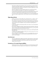 5
5 -
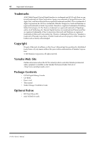 6
6 -
 7
7 -
8
-
9
-
10
-
11
-
12
-
13
-
14
-
15
-
16
-
17
-
18
-
19
-
20
-
21
-
22
-
23
-
24
-
25
-
26
-
27
-
28
-
29
-
30
-
31
-
32
-
33
-
34
-
35
-
36
-
37
-
38
-
39
-
40
-
41
-
42
-
43
-
44
-
45
-
46
-
47
-
48
-
49
-
50
-
51
-
52
-
53
-
54
-
55
-
56
-
57
-
58
-
59
-
60
-
61
-
62
-
63
-
64
-
65
-
66
-
67
-
68
-
69
-
70
-
71
-
72
-
73
-
74
-
75
-
76
-
77
-
78
-
79
-
80
-
81
-
82
-
83
-
84
-
85
-
86
-
87
-
88
-
89
-
90
-
91
-
92
-
93
-
94
-
95
-
96
-
97
-
98
-
99
-
100
-
101
-
102
-
103
-
104
-
105
-
106
-
107
-
108
-
109
-
110
-
111
-
112
-
113
-
114
-
115
-
116
-
117
-
118
-
119
-
120
-
121
-
122
-
123
-
124
-
125
-
126
-
127
-
128
-
129
-
130
-
131
-
132
-
133
-
134
-
135
-
136
-
137
-
138
-
139
-
140
-
141
-
142
-
143
-
144
-
145
-
146
-
147
-
148
-
149
-
150
-
151
-
152
-
153
-
154
-
155
-
156
-
157
-
158
-
159
-
160
-
161
-
162
-
163
-
164
-
165
-
166
-
167
-
168
-
169
-
170
-
171
-
172
-
173
-
174
-
175
-
176
-
177
-
178
-
179
-
180
-
181
-
182
-
183
-
184
-
185
-
186
-
187
-
188
-
189
-
190
-
191
-
192
-
193
-
194
-
195
-
196
-
197
-
198
-
199
-
200
-
201
-
202
-
203
-
204
-
205
-
206
-
207
-
208
-
209
-
210
-
211
-
212
-
213
-
214
-
215
-
216
-
217
-
218
-
219
-
220
-
221
-
222
-
223
-
224
-
225
-
226
-
227
-
228
-
229
-
230
-
231
-
232
-
233
-
234
-
235
-
236
-
237
-
238
-
239
-
240
-
241
-
242
-
243
-
244
-
245
-
246
-
247
-
248
-
249
-
250
-
251
-
252
-
253
-
254
-
255
-
256
-
257
-
258
-
259
-
260
-
261
-
262
-
263
-
264
-
265
-
266
-
267
-
268
-
269
-
270
-
271
-
272
-
273
-
274
-
275
-
276
-
277
-
278
-
279
-
280
-
281
-
282
-
283
-
284
-
285
-
286
-
287
-
288
-
289
-
290
-
291
-
292
-
293
-
294
-
295
-
296
-
297
-
298
-
299
-
300
-
301
-
302
-
303
-
304
-
305
-
306
-
307
-
308
-
309
-
310
-
311
-
312
-
313
-
314
-
315
-
316
-
317
-
318
-
319
-
320
-
321
-
322
-
323
-
324
-
325
-
326
-
327
-
328
-
329
-
330
-
331
-
332
-
333
-
334
 |
 |

E
Owner’s Manual
Keep This Manual For Future Reference.