Yamaha 01V96 Owner's Manual - Page 262
RING MOD., MOD. FILTER, DISTORTION, Parameter, Range, Description, SOURCE, OSC FREQ, FM FREQ.
 |
View all Yamaha 01V96 manuals
Add to My Manuals
Save this manual to your list of manuals |
Page 262 highlights
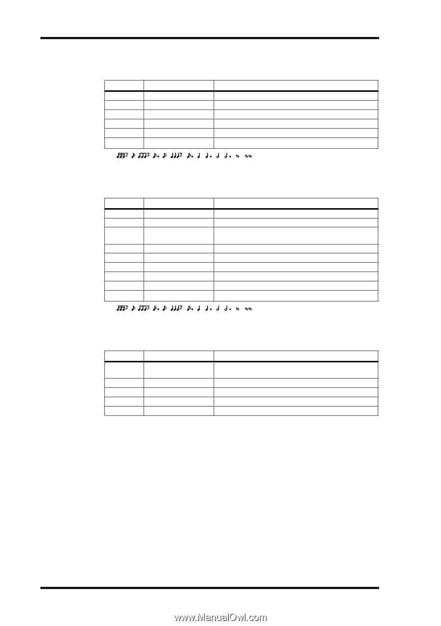
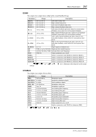
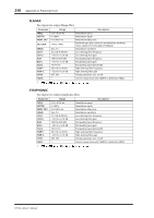
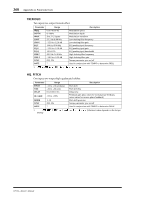
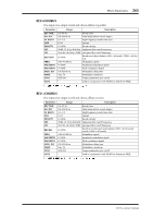
262 Appendix A: Parameter Lists RING MOD. Two input, two output ring modulator. Parameter Range SOURCE OSC FREQ FM FREQ. FM DEPTH SYNC NOTE FM OSC, SELF 0.0-5000.0 Hz 0.05-40.00 Hz 0-100% OFF, ON 1 Description Modulation source: oscillator or input signal Oscillator frequency Oscillator frequency modulation speed Oscillator frequency modulation depth Tempo parameter sync on/off Used in conjunction with TEMPO to determine FM FREQ 1. MOD. FILTER Two input, two output modulation filter. Parameter FREQ. DEPTH Range 0.05-40.00 Hz 0-100% PHASE 0.00-354.38 degrees TYPE OFFSET RESO. LEVEL SYNC NOTE LPF, HPF, BPF 0-100 0-20 0-100 OFF, ON 1 Description Modulation speed Modulation depth Left-channel modulation and right-channel modulation phase difference Filter type: low pass, high pass, band pass Filter frequency offset Filter resonance Output level Tempo parameter sync on/off Used in conjunction with TEMPO to determine FREQ 1. DISTORTION One input, two output distortion effect. Parameter DST TYPE DRIVE MASTER TONE N. GATE Range DST1, DST2, OVD1, OVD2, CRUNCH 0-100 0-100 -10 to +10 0-20 Description Distortion type (DST = distortion, OVD = overdrive) Distortion drive Master volume Tone Noise reduction 01V96-Owner's Manual
-
 1
1 -
2
-
3
-
4
-
5
-
6
-
7
-
8
-
9
-
10
-
11
-
12
-
13
-
14
-
15
-
16
-
17
-
18
-
19
-
20
-
21
-
22
-
23
-
24
-
25
-
26
-
27
-
28
-
29
-
30
-
31
-
32
-
33
-
34
-
35
-
36
-
37
-
38
-
39
-
40
-
41
-
42
-
43
-
44
-
45
-
46
-
47
-
48
-
49
-
50
-
51
-
52
-
53
-
54
-
55
-
56
-
57
-
58
-
59
-
60
-
61
-
62
-
63
-
64
-
65
-
66
-
67
-
68
-
69
-
70
-
71
-
72
-
73
-
74
-
75
-
76
-
77
-
78
-
79
-
80
-
81
-
82
-
83
-
84
-
85
-
86
-
87
-
88
-
89
-
90
-
91
-
92
-
93
-
94
-
95
-
96
-
97
-
98
-
99
-
100
-
101
-
102
-
103
-
104
-
105
-
106
-
107
-
108
-
109
-
110
-
111
-
112
-
113
-
114
-
115
-
116
-
117
-
118
-
119
-
120
-
121
-
122
-
123
-
124
-
125
-
126
-
127
-
128
-
129
-
130
-
131
-
132
-
133
-
134
-
135
-
136
-
137
-
138
-
139
-
140
-
141
-
142
-
143
-
144
-
145
-
146
-
147
-
148
-
149
-
150
-
151
-
152
-
153
-
154
-
155
-
156
-
157
-
158
-
159
-
160
-
161
-
162
-
163
-
164
-
165
-
166
-
167
-
168
-
169
-
170
-
171
-
172
-
173
-
174
-
175
-
176
-
177
-
178
-
179
-
180
-
181
-
182
-
183
-
184
-
185
-
186
-
187
-
188
-
189
-
190
-
191
-
192
-
193
-
194
-
195
-
196
-
197
-
198
-
199
-
200
-
201
-
202
-
203
-
204
-
205
-
206
-
207
-
208
-
209
-
210
-
211
-
212
-
213
-
214
-
215
-
216
-
217
-
218
-
219
-
220
-
221
-
222
-
223
-
224
-
225
-
226
-
227
-
228
-
229
-
230
-
231
-
232
-
233
-
234
-
235
-
236
-
237
-
238
-
239
-
240
-
241
-
242
-
243
-
244
-
245
-
246
-
247
-
248
-
249
-
250
-
251
-
252
-
253
-
254
-
255
-
256
-
 257
257 -
 258
258 -
 259
259 -
 260
260 -
 261
261 -
 262
262 -
 263
263 -
 264
264 -
 265
265 -
 266
266 -
 267
267 -
268
-
269
-
270
-
271
-
272
-
273
-
274
-
275
-
276
-
277
-
278
-
279
-
280
-
281
-
282
-
283
-
284
-
285
-
286
-
287
-
288
-
289
-
290
-
291
-
292
-
293
-
294
-
295
-
296
-
297
-
298
-
299
-
300
-
301
-
302
-
303
-
304
-
305
-
306
-
307
-
308
-
309
-
310
-
311
-
312
-
313
-
314
-
315
-
316
-
317
-
318
-
319
-
320
-
321
-
322
-
323
-
324
-
325
-
326
-
327
-
328
-
329
-
330
-
331
-
332
-
333
-
334
 |
 |