Yamaha 01V96 Owner's Manual - Page 17
ST IN FADER MODE ST IN] button, SEL] buttons, Level controls, HOME] button
 |
View all Yamaha 01V96 manuals
Add to My Manuals
Save this manual to your list of manuals |
Page 17 highlights
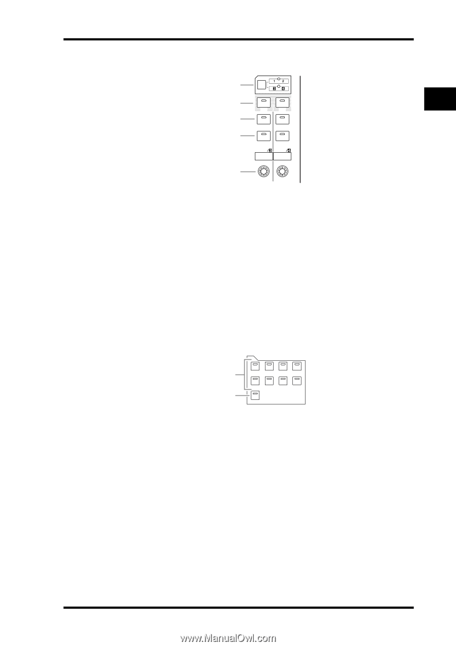
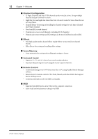
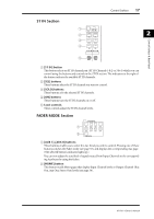
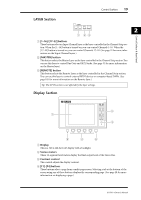
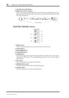
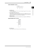
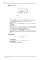
Control Surface 17 Control Surface & Rear Panel ST IN Section 1 2 3 4 ST IN SEL SEL SOLO SOLO ON ST IN 1 ON ST IN 2 2 5 A [ST IN] button This button selects an ST IN channel pair (ST IN Channels 1 & 2 or 3 & 4) which you can control using the buttons and controls in the ST IN section. The indicators to the right of the button indicate the available ST IN channels. B [SEL] buttons These buttons select the ST IN channel you want to control. C [SOLO] buttons These buttons solo the selected ST IN channels. D [ON] buttons These buttons turn the ST IN channels on or off. E Level controls These controls adjust the ST IN channel levels. FADER MODE Section 1 2 FADER MODE AUX 1 AUX 2 AUX 3 AUX 4 AUX 5 AUX 6 AUX 7 AUX 8 HOME (METER) A [AUX 1]-[AUX 8] buttons These buttons enable you to select the Aux Send you wish to control. Pressing one of these buttons switches the Fader mode (see page 33), and displays the corresponding Aux page. (The selected button's indicator lights up.) You can now adjust the send level of signals routed from Input Channels to the corresponding Aux buses by using the faders. B [HOME] button This button recalls Meter pages that display Input Channel levels or Output Channel (Bus Out, Aux Out, Stereo Out) levels (see page 34). 01V96-Owner's Manual
-
 1
1 -
2
-
3
-
4
-
5
-
6
-
7
-
8
-
9
-
10
-
11
-
 12
12 -
 13
13 -
 14
14 -
 15
15 -
 16
16 -
 17
17 -
 18
18 -
 19
19 -
 20
20 -
 21
21 -
 22
22 -
23
-
24
-
25
-
26
-
27
-
28
-
29
-
30
-
31
-
32
-
33
-
34
-
35
-
36
-
37
-
38
-
39
-
40
-
41
-
42
-
43
-
44
-
45
-
46
-
47
-
48
-
49
-
50
-
51
-
52
-
53
-
54
-
55
-
56
-
57
-
58
-
59
-
60
-
61
-
62
-
63
-
64
-
65
-
66
-
67
-
68
-
69
-
70
-
71
-
72
-
73
-
74
-
75
-
76
-
77
-
78
-
79
-
80
-
81
-
82
-
83
-
84
-
85
-
86
-
87
-
88
-
89
-
90
-
91
-
92
-
93
-
94
-
95
-
96
-
97
-
98
-
99
-
100
-
101
-
102
-
103
-
104
-
105
-
106
-
107
-
108
-
109
-
110
-
111
-
112
-
113
-
114
-
115
-
116
-
117
-
118
-
119
-
120
-
121
-
122
-
123
-
124
-
125
-
126
-
127
-
128
-
129
-
130
-
131
-
132
-
133
-
134
-
135
-
136
-
137
-
138
-
139
-
140
-
141
-
142
-
143
-
144
-
145
-
146
-
147
-
148
-
149
-
150
-
151
-
152
-
153
-
154
-
155
-
156
-
157
-
158
-
159
-
160
-
161
-
162
-
163
-
164
-
165
-
166
-
167
-
168
-
169
-
170
-
171
-
172
-
173
-
174
-
175
-
176
-
177
-
178
-
179
-
180
-
181
-
182
-
183
-
184
-
185
-
186
-
187
-
188
-
189
-
190
-
191
-
192
-
193
-
194
-
195
-
196
-
197
-
198
-
199
-
200
-
201
-
202
-
203
-
204
-
205
-
206
-
207
-
208
-
209
-
210
-
211
-
212
-
213
-
214
-
215
-
216
-
217
-
218
-
219
-
220
-
221
-
222
-
223
-
224
-
225
-
226
-
227
-
228
-
229
-
230
-
231
-
232
-
233
-
234
-
235
-
236
-
237
-
238
-
239
-
240
-
241
-
242
-
243
-
244
-
245
-
246
-
247
-
248
-
249
-
250
-
251
-
252
-
253
-
254
-
255
-
256
-
257
-
258
-
259
-
260
-
261
-
262
-
263
-
264
-
265
-
266
-
267
-
268
-
269
-
270
-
271
-
272
-
273
-
274
-
275
-
276
-
277
-
278
-
279
-
280
-
281
-
282
-
283
-
284
-
285
-
286
-
287
-
288
-
289
-
290
-
291
-
292
-
293
-
294
-
295
-
296
-
297
-
298
-
299
-
300
-
301
-
302
-
303
-
304
-
305
-
306
-
307
-
308
-
309
-
310
-
311
-
312
-
313
-
314
-
315
-
316
-
317
-
318
-
319
-
320
-
321
-
322
-
323
-
324
-
325
-
326
-
327
-
328
-
329
-
330
-
331
-
332
-
333
-
334
 |
 |