Yamaha 01V96 Owner's Manual - Page 128
ON/OFF, ORDER, nels, or slot input channels to be patched to the Insert In.
 |
View all Yamaha 01V96 manuals
Add to My Manuals
Save this manual to your list of manuals |
Page 128 highlights
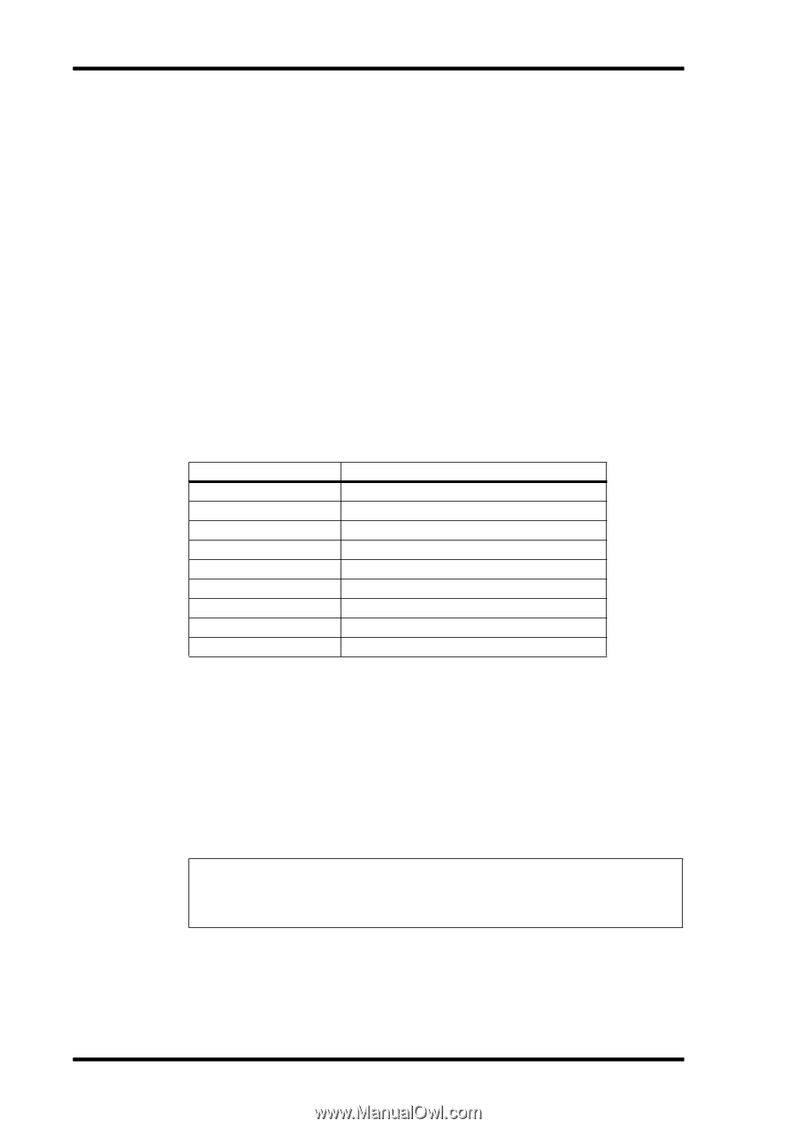
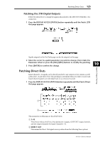
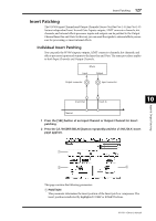
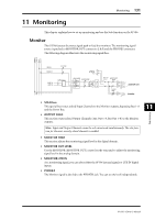
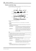
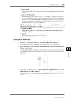
128 Chapter 10-Input & Output Patching B INSERT section • ON/OFF This button turns the Insert on or off. • OUT This parameter enables you to select outputs, ADAT OUT channels, slot output channels, or internal effects inputs as the Insert Out destination. • IN This parameter enables you to select inputs, ADAT IN channels, slot input channels, or internal effects outputs as the Insert In source. C COMP section • ON/OFF This button turns the compressor on or off. • ORDER This parameter determines the order of Insert patch and compressor when they are inserted at the same signal path point. With the "COMP → INS" setting, signals pass through the compressor first, then the Insert. With the "INS → COMP" setting, signals pass through the Insert first, then the compressor. 3 Move the cursor to the OUT parameter box, then rotate the Parameter wheel or press the [INC]/[DEC] buttons to select the desired outputs, slot channels, or internal effects inputs to be patched to Insert Out. The parameter indicators are explained below: Parameter values - ADAT 1-ADAT 8 SL-01-SL-16 OMNI1-OMNI4 2TD-L/2TD-R FX1-1/FX1-2 FX2-1/FX2-2 FX3-1/FX3-2 FX4-1/FX4-2 Description No assignment ADAT OUT Output Channels 1-8 Slot Channels 1-16 OMNI OUT connectors 1-4 2TR OUT DIGITAL (L/R) Inputs 1 & 2 of Internal Effects Processor 1 Inputs 1 & 2 of Internal Effects Processor 2 Inputs 1 & 2 of Internal Effects Processor 3 Inputs 1 & 2 of Internal Effects Processor 4 4 Press [ENTER] to confirm the change. If you move the cursor to another parameter box or display another page before you press the [ENTER] button, all settings on this page will be cancelled. 5 Move the cursor to the desired IN parameter box, then rotate the Parameter wheel or press the [INC]/[DEC] buttons to select the inputs, ADAT IN channels, or slot input channels to be patched to the Insert In. Refer to the explanation regarding the Input Patch for more information on the parameter values (see page 122). 6 Press [ENTER] to confirm the change. Tip: Move the cursor to an empty OUT or IN parameter box and press the [ENTER] button. The Patch Select window appears. Rotate the Parameter wheel or press the cursor buttons to select an item to be patched, then press [ENTER]. Move the cursor to the YES button, then press [ENTER]. The selected item is now patched. 7 To enable the specified Insert patch, move the cursor to the ON/OFF button in the INSERT section, and press [ENTER] to turn it on or off. 01V96-Owner's Manual
-
 1
1 -
2
-
3
-
4
-
5
-
6
-
7
-
8
-
9
-
10
-
11
-
12
-
13
-
14
-
15
-
16
-
17
-
18
-
19
-
20
-
21
-
22
-
23
-
24
-
25
-
26
-
27
-
28
-
29
-
30
-
31
-
32
-
33
-
34
-
35
-
36
-
37
-
38
-
39
-
40
-
41
-
42
-
43
-
44
-
45
-
46
-
47
-
48
-
49
-
50
-
51
-
52
-
53
-
54
-
55
-
56
-
57
-
58
-
59
-
60
-
61
-
62
-
63
-
64
-
65
-
66
-
67
-
68
-
69
-
70
-
71
-
72
-
73
-
74
-
75
-
76
-
77
-
78
-
79
-
80
-
81
-
82
-
83
-
84
-
85
-
86
-
87
-
88
-
89
-
90
-
91
-
92
-
93
-
94
-
95
-
96
-
97
-
98
-
99
-
100
-
101
-
102
-
103
-
104
-
105
-
106
-
107
-
108
-
109
-
110
-
111
-
112
-
113
-
114
-
115
-
116
-
117
-
118
-
119
-
120
-
121
-
122
-
 123
123 -
 124
124 -
 125
125 -
 126
126 -
 127
127 -
 128
128 -
 129
129 -
 130
130 -
 131
131 -
 132
132 -
 133
133 -
134
-
135
-
136
-
137
-
138
-
139
-
140
-
141
-
142
-
143
-
144
-
145
-
146
-
147
-
148
-
149
-
150
-
151
-
152
-
153
-
154
-
155
-
156
-
157
-
158
-
159
-
160
-
161
-
162
-
163
-
164
-
165
-
166
-
167
-
168
-
169
-
170
-
171
-
172
-
173
-
174
-
175
-
176
-
177
-
178
-
179
-
180
-
181
-
182
-
183
-
184
-
185
-
186
-
187
-
188
-
189
-
190
-
191
-
192
-
193
-
194
-
195
-
196
-
197
-
198
-
199
-
200
-
201
-
202
-
203
-
204
-
205
-
206
-
207
-
208
-
209
-
210
-
211
-
212
-
213
-
214
-
215
-
216
-
217
-
218
-
219
-
220
-
221
-
222
-
223
-
224
-
225
-
226
-
227
-
228
-
229
-
230
-
231
-
232
-
233
-
234
-
235
-
236
-
237
-
238
-
239
-
240
-
241
-
242
-
243
-
244
-
245
-
246
-
247
-
248
-
249
-
250
-
251
-
252
-
253
-
254
-
255
-
256
-
257
-
258
-
259
-
260
-
261
-
262
-
263
-
264
-
265
-
266
-
267
-
268
-
269
-
270
-
271
-
272
-
273
-
274
-
275
-
276
-
277
-
278
-
279
-
280
-
281
-
282
-
283
-
284
-
285
-
286
-
287
-
288
-
289
-
290
-
291
-
292
-
293
-
294
-
295
-
296
-
297
-
298
-
299
-
300
-
301
-
302
-
303
-
304
-
305
-
306
-
307
-
308
-
309
-
310
-
311
-
312
-
313
-
314
-
315
-
316
-
317
-
318
-
319
-
320
-
321
-
322
-
323
-
324
-
325
-
326
-
327
-
328
-
329
-
330
-
331
-
332
-
333
-
334
 |
 |