Yamaha 01V96 Owner's Manual - Page 131
Monitoring, Monitor - logic
 |
View all Yamaha 01V96 manuals
Add to My Manuals
Save this manual to your list of manuals |
Page 131 highlights
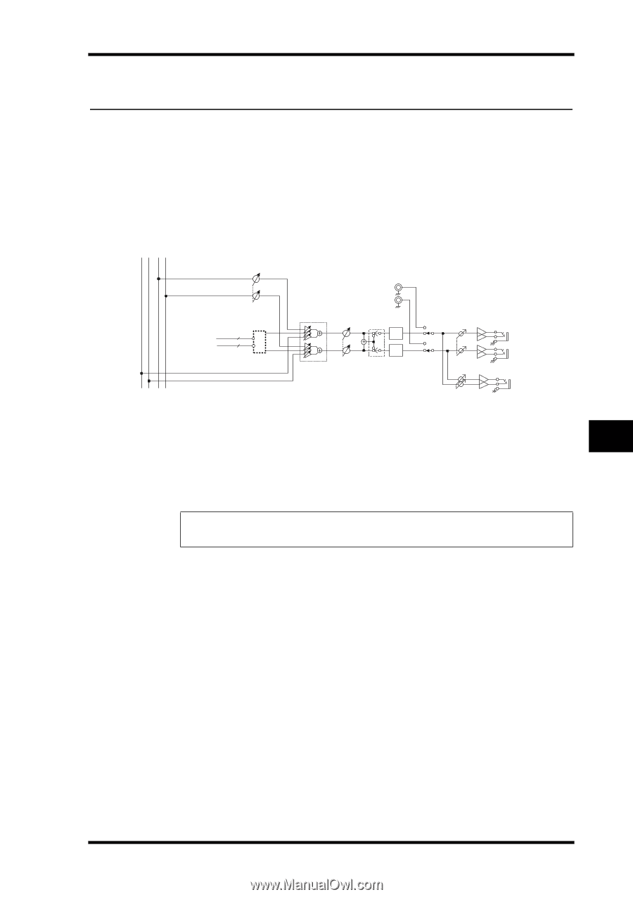
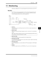
Monitoring 131 11 Monitoring This chapter explains how to set up monitoring and use the Solo function on the 01V96. Monitor The 01V96 features the stereo signal path to feed the monitors. The monitoring signal source is patched to MONITOR OUT connectors L & R and the PHONES connector. The following diagram illustrates the monitoring signal flow. STEREO L STEREO R SOLO L SOLO R MONO SOLO L SOLO R SOLO TRIM BUS1-8 AUX1-8 OUTPUT SOLO 8 8 L [2TR IN] RCA R SOLO LOGIC MONITOR TRIM DA DA MONITOR MONITOR OUT /2TR IN LEVEL PHONES LEVEL L [MONITOR OUT] R [PHONES] • SOLO bus This special bus routes soloed Input Channels to the Monitor outputs, bypassing Bus 1-8 and the Stereo Bus. • OUTPUT SOLO This section routes soloed Output Channels (Aux Out 1-8, Bus Out 1-8) to the Monitor outputs. Note: Input and Output Channels cannot be solo-monitored simultaneously. The solo function for the most-recently soloed channels is enabled. • MONITOR TRIM This section adjusts the monitoring signal level in the digital domain. • MONITOR OUT LEVEL Use the MONITOR [MONITOR OUT] control on the top panel to adjust the monitoring signal level in the analog domain. • MONITOR/2TR IN As a monitoring signal, you can select either the 01V96 internal signals or 2TR IN digital inputs. • PHONES The Monitor signal is also fed to the PHONES jack. You can set the level independently. Monitoring 11 01V96-Owner's Manual
-
 1
1 -
2
-
3
-
4
-
5
-
6
-
7
-
8
-
9
-
10
-
11
-
12
-
13
-
14
-
15
-
16
-
17
-
18
-
19
-
20
-
21
-
22
-
23
-
24
-
25
-
26
-
27
-
28
-
29
-
30
-
31
-
32
-
33
-
34
-
35
-
36
-
37
-
38
-
39
-
40
-
41
-
42
-
43
-
44
-
45
-
46
-
47
-
48
-
49
-
50
-
51
-
52
-
53
-
54
-
55
-
56
-
57
-
58
-
59
-
60
-
61
-
62
-
63
-
64
-
65
-
66
-
67
-
68
-
69
-
70
-
71
-
72
-
73
-
74
-
75
-
76
-
77
-
78
-
79
-
80
-
81
-
82
-
83
-
84
-
85
-
86
-
87
-
88
-
89
-
90
-
91
-
92
-
93
-
94
-
95
-
96
-
97
-
98
-
99
-
100
-
101
-
102
-
103
-
104
-
105
-
106
-
107
-
108
-
109
-
110
-
111
-
112
-
113
-
114
-
115
-
116
-
117
-
118
-
119
-
120
-
121
-
122
-
123
-
124
-
125
-
 126
126 -
 127
127 -
 128
128 -
 129
129 -
 130
130 -
 131
131 -
 132
132 -
 133
133 -
 134
134 -
 135
135 -
 136
136 -
137
-
138
-
139
-
140
-
141
-
142
-
143
-
144
-
145
-
146
-
147
-
148
-
149
-
150
-
151
-
152
-
153
-
154
-
155
-
156
-
157
-
158
-
159
-
160
-
161
-
162
-
163
-
164
-
165
-
166
-
167
-
168
-
169
-
170
-
171
-
172
-
173
-
174
-
175
-
176
-
177
-
178
-
179
-
180
-
181
-
182
-
183
-
184
-
185
-
186
-
187
-
188
-
189
-
190
-
191
-
192
-
193
-
194
-
195
-
196
-
197
-
198
-
199
-
200
-
201
-
202
-
203
-
204
-
205
-
206
-
207
-
208
-
209
-
210
-
211
-
212
-
213
-
214
-
215
-
216
-
217
-
218
-
219
-
220
-
221
-
222
-
223
-
224
-
225
-
226
-
227
-
228
-
229
-
230
-
231
-
232
-
233
-
234
-
235
-
236
-
237
-
238
-
239
-
240
-
241
-
242
-
243
-
244
-
245
-
246
-
247
-
248
-
249
-
250
-
251
-
252
-
253
-
254
-
255
-
256
-
257
-
258
-
259
-
260
-
261
-
262
-
263
-
264
-
265
-
266
-
267
-
268
-
269
-
270
-
271
-
272
-
273
-
274
-
275
-
276
-
277
-
278
-
279
-
280
-
281
-
282
-
283
-
284
-
285
-
286
-
287
-
288
-
289
-
290
-
291
-
292
-
293
-
294
-
295
-
296
-
297
-
298
-
299
-
300
-
301
-
302
-
303
-
304
-
305
-
306
-
307
-
308
-
309
-
310
-
311
-
312
-
313
-
314
-
315
-
316
-
317
-
318
-
319
-
320
-
321
-
322
-
323
-
324
-
325
-
326
-
327
-
328
-
329
-
330
-
331
-
332
-
333
-
334
 |
 |