Yamaha 01V96 Owner's Manual - Page 14
AD Input AINPUT connectors A/B BINPUT connectors 13-16 CINSERT I/O connectors - owner s manual
 |
View all Yamaha 01V96 manuals
Add to My Manuals
Save this manual to your list of manuals |
Page 14 highlights
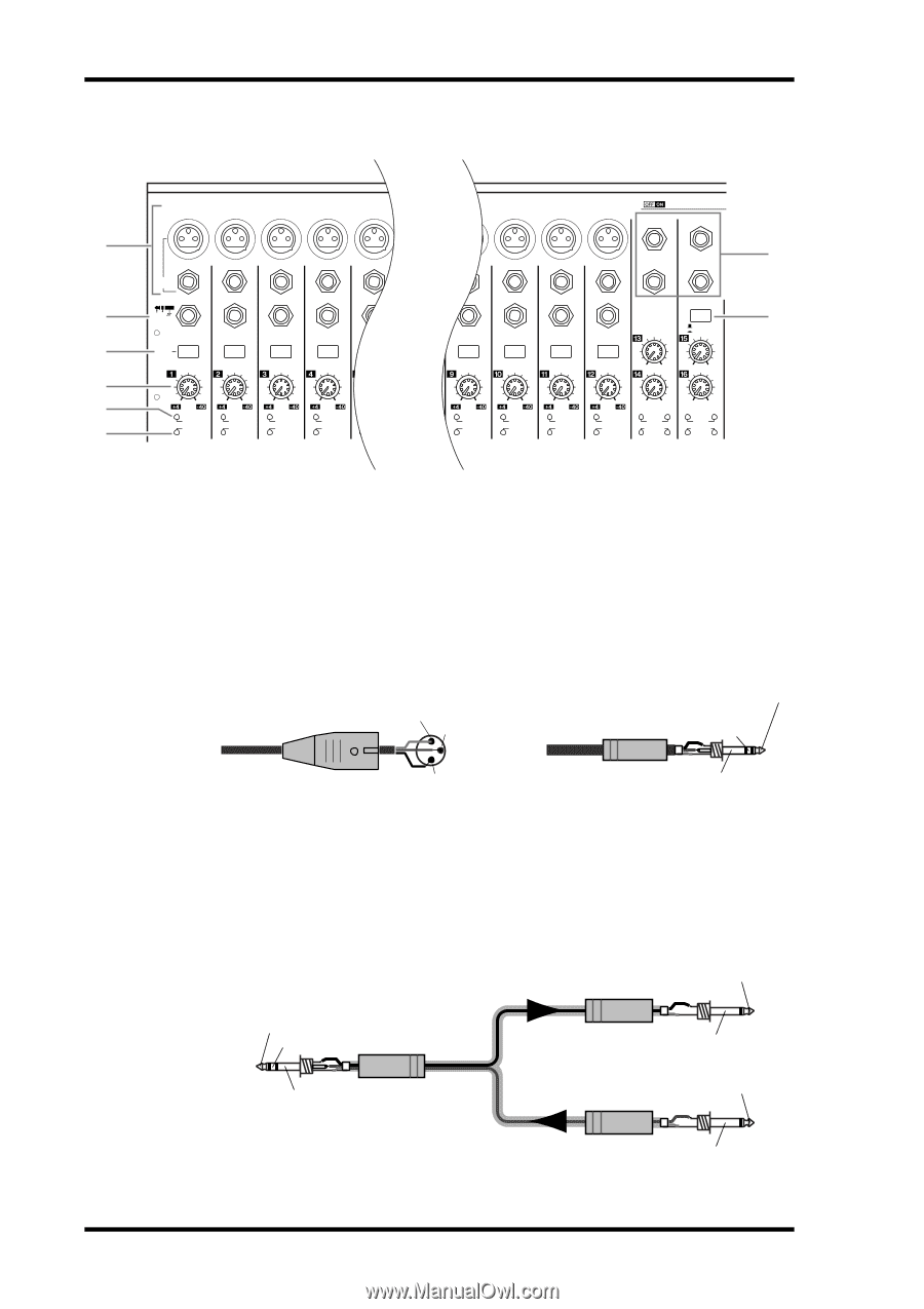
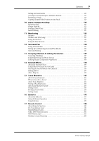
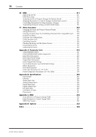
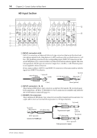
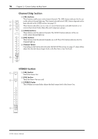
14 Chapter 2-Control Surface & Rear Panel AD Input Section 1 3 4 5 6 7 1 2 3 4 5 A A A A A B B B B B INPUT (BAL) INSERT OUT IN (UNBAL) INSERT I/O INSERT I/O INSERT I/O INSERT I/O INSERT I/O PAD 20dB 20dB 20dB 20dB 20dB -16 -60 GAIN PEAK SIGNAL -16 -60 GAIN PEAK SIGNAL -16 -60 GAIN PEAK SIGNAL -16 -60 GAIN PEAK SIGNAL -16 -60 GAIN PEAK SIGNAL CH1-4 9 10 11 12 13 15 A A A A B B B B 14 16 INSERT I/O INSERT I/O INSERT I/O INSERT I/O CH15/16 2TR IN 20dB 20dB 20dB 20dB +4 GAIN -26 +4 GAIN -26 -16 -60 GAIN PEAK SIGNAL -16 -60 GAIN PEAK SIGNAL -16 -60 GAIN PEAK SIGNAL -16 -60 GAIN +4 GAIN -26 +4 GAIN -26 PEAK SIGNAL 13 PEAK SIGNAL 14 15 PEAK SIGNAL 16 2 8 A INPUT connectors A/B INPUT A connectors are balanced XLR-3-31-type connectors that accept line-level and microphone signals. Each of the phantom [+48V] switches on the rear panel turns on or off the +48V phantom power feed to the corresponding input. INPUT B connectors are balanced TRS phone-type connectors that accept line-level and microphone signals. The nominal signal level of both types of connectors ranges from -60 dB to +4 dB. Phantom power is not supplied to these connectors. If you connect cables to INPUT A and INPUT B connectors of the same number, only the signal from INPUT B is effective. Male XLR plug 1 (ground) 3 (cold) 1/4" TRS phone plug Tip (hot) Ring (cold) 2 (hot) Sleeve (ground) B INPUT connectors 13-16 These balanced TRS phone-type connectors accept line-level signals. The nominal signal level ranges from -26 dB to +4 dB. INPUT 15 & 16 connectors are available only when the AD 15/16 button is turned off (page 15). C INSERT I/O connectors These unbalanced TRS phone-type connectors are used for channel insert ins and outs. Use a split cable to insert an external effects processor to AD input channels. 1/4" phone plug Tip (send) Tip (send) Ring (return) 1/4" phone plug Sleeve (ground) Connect to INSERT jack To processor's input 1/4" phone plug Sleeve (ground) Tip (return) Sleeve (ground) From processor's output 01V96-Owner's Manual
-
 1
1 -
2
-
3
-
4
-
5
-
6
-
7
-
8
-
 9
9 -
 10
10 -
 11
11 -
 12
12 -
 13
13 -
 14
14 -
 15
15 -
 16
16 -
 17
17 -
 18
18 -
 19
19 -
20
-
21
-
22
-
23
-
24
-
25
-
26
-
27
-
28
-
29
-
30
-
31
-
32
-
33
-
34
-
35
-
36
-
37
-
38
-
39
-
40
-
41
-
42
-
43
-
44
-
45
-
46
-
47
-
48
-
49
-
50
-
51
-
52
-
53
-
54
-
55
-
56
-
57
-
58
-
59
-
60
-
61
-
62
-
63
-
64
-
65
-
66
-
67
-
68
-
69
-
70
-
71
-
72
-
73
-
74
-
75
-
76
-
77
-
78
-
79
-
80
-
81
-
82
-
83
-
84
-
85
-
86
-
87
-
88
-
89
-
90
-
91
-
92
-
93
-
94
-
95
-
96
-
97
-
98
-
99
-
100
-
101
-
102
-
103
-
104
-
105
-
106
-
107
-
108
-
109
-
110
-
111
-
112
-
113
-
114
-
115
-
116
-
117
-
118
-
119
-
120
-
121
-
122
-
123
-
124
-
125
-
126
-
127
-
128
-
129
-
130
-
131
-
132
-
133
-
134
-
135
-
136
-
137
-
138
-
139
-
140
-
141
-
142
-
143
-
144
-
145
-
146
-
147
-
148
-
149
-
150
-
151
-
152
-
153
-
154
-
155
-
156
-
157
-
158
-
159
-
160
-
161
-
162
-
163
-
164
-
165
-
166
-
167
-
168
-
169
-
170
-
171
-
172
-
173
-
174
-
175
-
176
-
177
-
178
-
179
-
180
-
181
-
182
-
183
-
184
-
185
-
186
-
187
-
188
-
189
-
190
-
191
-
192
-
193
-
194
-
195
-
196
-
197
-
198
-
199
-
200
-
201
-
202
-
203
-
204
-
205
-
206
-
207
-
208
-
209
-
210
-
211
-
212
-
213
-
214
-
215
-
216
-
217
-
218
-
219
-
220
-
221
-
222
-
223
-
224
-
225
-
226
-
227
-
228
-
229
-
230
-
231
-
232
-
233
-
234
-
235
-
236
-
237
-
238
-
239
-
240
-
241
-
242
-
243
-
244
-
245
-
246
-
247
-
248
-
249
-
250
-
251
-
252
-
253
-
254
-
255
-
256
-
257
-
258
-
259
-
260
-
261
-
262
-
263
-
264
-
265
-
266
-
267
-
268
-
269
-
270
-
271
-
272
-
273
-
274
-
275
-
276
-
277
-
278
-
279
-
280
-
281
-
282
-
283
-
284
-
285
-
286
-
287
-
288
-
289
-
290
-
291
-
292
-
293
-
294
-
295
-
296
-
297
-
298
-
299
-
300
-
301
-
302
-
303
-
304
-
305
-
306
-
307
-
308
-
309
-
310
-
311
-
312
-
313
-
314
-
315
-
316
-
317
-
318
-
319
-
320
-
321
-
322
-
323
-
324
-
325
-
326
-
327
-
328
-
329
-
330
-
331
-
332
-
333
-
334
 |
 |