Yamaha 01V96 Owner's Manual - Page 124
Changing the Signal Path to the ADAT OUT Connector, Slot, or OMNI OUT connectors
 |
View all Yamaha 01V96 manuals
Add to My Manuals
Save this manual to your list of manuals |
Page 124 highlights
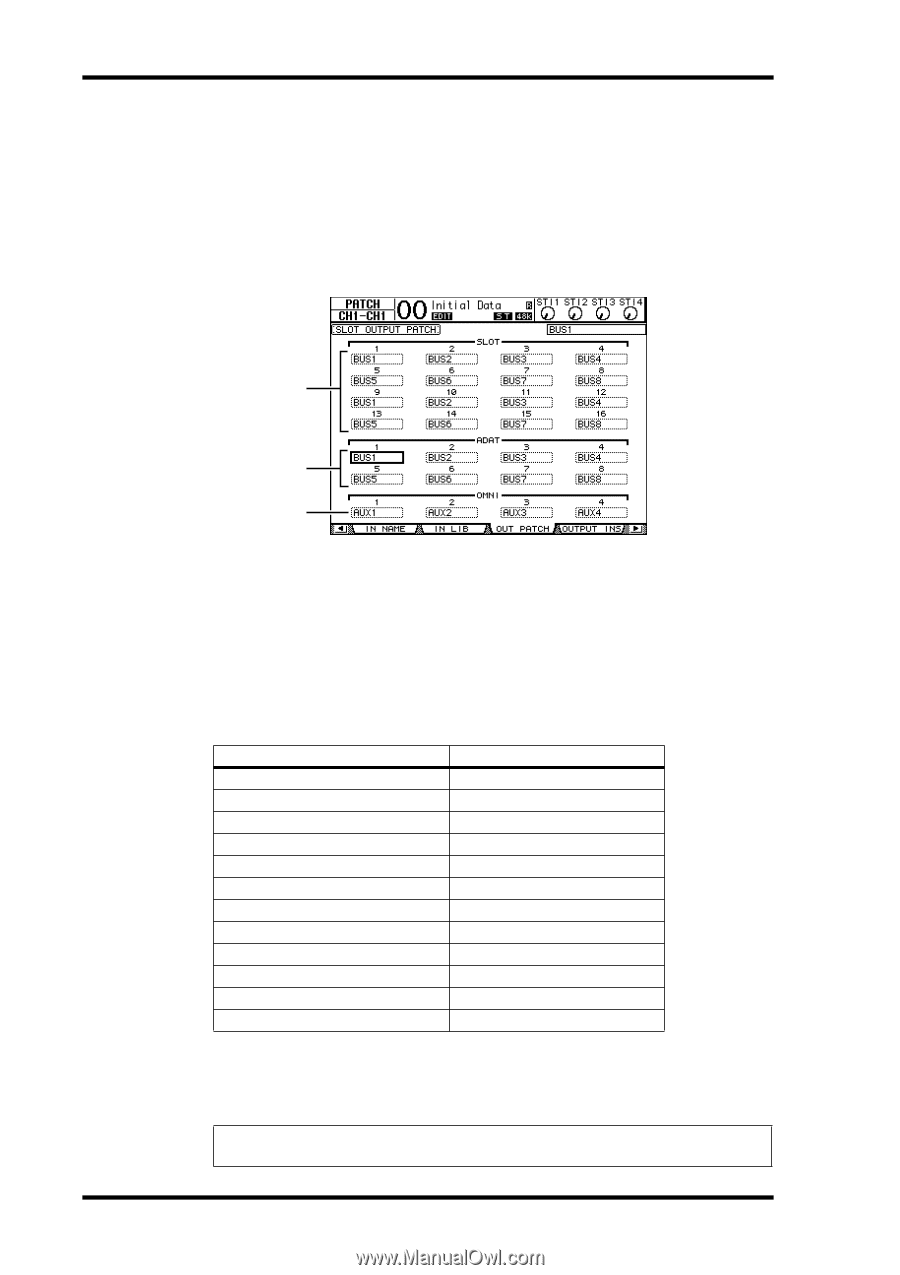
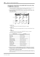
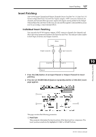
124 Chapter 10-Input & Output Patching Changing the Signal Path to the ADAT OUT Connector, Slot, or OMNI OUT connectors Follow the steps below to change the signal path patched to the ADAT OUT connector, the optional mini-YGDAI card installed in the slot, or the OMNI OUT connectors. 1 Press the DISPLAY ACCESS [PATCH] button repeatedly until the Patch | Out Patch page appears. Each parameter box displays the currently-patched signal path. 1 2 3 A SLOT 1-16 These parameter boxes set the routing of Slot Channel 1-16 signals. B ADAT 1-8 These parameter boxes set the routing of ADAT OUT connector output channel 1-8 signals. C OMNI 1-4 These parameter boxes set the routing of OMNI OUT connector 1-4 signals. The parameter indicators are explained below: Parameter value - BUS1-BUS8 AUX1-AUX8 ST L/R INS CH1-INS CH32 INS BUS1-INS BUS8 INS AUX1-INS AUX8 INS ST-L/ST-R CAS BUS1-BUS8 CAS AUX1-AUX8 CAS ST-L/ST-R CASSOLOL/CASSOLOR Description No assignment Bus Out 1-8 signal Aux Out 1-8 signal Stereo Out signal Input Channel 1-32 Insert Out Bus Out 1-8 Insert Out Aux Out 1-8 Insert Out Stereo Out Insert Out Bus 1-8 Cascade Outs Aux Bus 1-8 Cascade Outs Stereo Bus Cascade Outs Solo Bus Cascade Outs 2 Move the cursor to a patch parameter you wish to change, then rotate the Parameter wheel or press the [INC]/[DEC] buttons to modify the patching. 3 Press [ENTER] to confirm the change. Tip: You can store the Output Patch settings to the Output Patch library. Refer to Chapter 16 for more information. 01V96-Owner's Manual
-
 1
1 -
2
-
3
-
4
-
5
-
6
-
7
-
8
-
9
-
10
-
11
-
12
-
13
-
14
-
15
-
16
-
17
-
18
-
19
-
20
-
21
-
22
-
23
-
24
-
25
-
26
-
27
-
28
-
29
-
30
-
31
-
32
-
33
-
34
-
35
-
36
-
37
-
38
-
39
-
40
-
41
-
42
-
43
-
44
-
45
-
46
-
47
-
48
-
49
-
50
-
51
-
52
-
53
-
54
-
55
-
56
-
57
-
58
-
59
-
60
-
61
-
62
-
63
-
64
-
65
-
66
-
67
-
68
-
69
-
70
-
71
-
72
-
73
-
74
-
75
-
76
-
77
-
78
-
79
-
80
-
81
-
82
-
83
-
84
-
85
-
86
-
87
-
88
-
89
-
90
-
91
-
92
-
93
-
94
-
95
-
96
-
97
-
98
-
99
-
100
-
101
-
102
-
103
-
104
-
105
-
106
-
107
-
108
-
109
-
110
-
111
-
112
-
113
-
114
-
115
-
116
-
117
-
118
-
 119
119 -
 120
120 -
 121
121 -
 122
122 -
 123
123 -
 124
124 -
 125
125 -
 126
126 -
 127
127 -
 128
128 -
 129
129 -
130
-
131
-
132
-
133
-
134
-
135
-
136
-
137
-
138
-
139
-
140
-
141
-
142
-
143
-
144
-
145
-
146
-
147
-
148
-
149
-
150
-
151
-
152
-
153
-
154
-
155
-
156
-
157
-
158
-
159
-
160
-
161
-
162
-
163
-
164
-
165
-
166
-
167
-
168
-
169
-
170
-
171
-
172
-
173
-
174
-
175
-
176
-
177
-
178
-
179
-
180
-
181
-
182
-
183
-
184
-
185
-
186
-
187
-
188
-
189
-
190
-
191
-
192
-
193
-
194
-
195
-
196
-
197
-
198
-
199
-
200
-
201
-
202
-
203
-
204
-
205
-
206
-
207
-
208
-
209
-
210
-
211
-
212
-
213
-
214
-
215
-
216
-
217
-
218
-
219
-
220
-
221
-
222
-
223
-
224
-
225
-
226
-
227
-
228
-
229
-
230
-
231
-
232
-
233
-
234
-
235
-
236
-
237
-
238
-
239
-
240
-
241
-
242
-
243
-
244
-
245
-
246
-
247
-
248
-
249
-
250
-
251
-
252
-
253
-
254
-
255
-
256
-
257
-
258
-
259
-
260
-
261
-
262
-
263
-
264
-
265
-
266
-
267
-
268
-
269
-
270
-
271
-
272
-
273
-
274
-
275
-
276
-
277
-
278
-
279
-
280
-
281
-
282
-
283
-
284
-
285
-
286
-
287
-
288
-
289
-
290
-
291
-
292
-
293
-
294
-
295
-
296
-
297
-
298
-
299
-
300
-
301
-
302
-
303
-
304
-
305
-
306
-
307
-
308
-
309
-
310
-
311
-
312
-
313
-
314
-
315
-
316
-
317
-
318
-
319
-
320
-
321
-
322
-
323
-
324
-
325
-
326
-
327
-
328
-
329
-
330
-
331
-
332
-
333
-
334
 |
 |