Yamaha 01V96 Owner's Manual - Page 15
Monitor Out & Headphones
 |
View all Yamaha 01V96 manuals
Add to My Manuals
Save this manual to your list of manuals |
Page 15 highlights
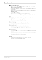
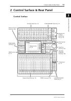
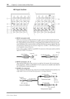
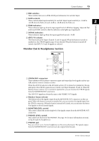
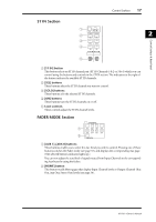
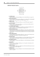
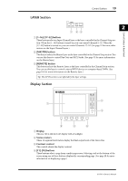
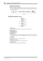
Control Surface 15 D PAD switches These switches turn on or off the 20 dB pad (attenuator) for each AD Input. E GAIN controls These controls adjust input sensitivity for each AD Input. Input sensitivity is -16 dB to -60 dB when the Pad is off, and +4 dB to -40 dB when the Pad is on. 2 Control Surface & Rear Panel F PEAK indicators These indicators light up when the input signal level is 3 dB below clipping. Adjust the Pad switch and GAIN control so that the indicator rarely lights up at signal peak. G SIGNAL indicators These indicators light up when the input signal level exceeds -34 dB. H AD15/16 selector This button selects AD Input Channel 15 and 16 signals. When the button is turned on (pushed in), the 2TR IN signals (page 24) are selected. When the button is turned off (raised), the INPUT 15 and 16 signals are selected. Monitor Out & Headphones Section 1 2 3 CH5-8 CH9-12 PHANTOM +48V L R IN OUT 2TR -10dBV (UNBAL) PHONES MONITOR 2TR IN 0 LEVEL10 MONITOR OUT 0 LEVEL10 PHONES 5 4 A 2TR IN/OUT connectors These unbalanced RCA phono connectors input and output line-level signals, and are typically used to connect a master recorder. When the AD15/16 selector in the AD Input section (8) is turned on (pushed in), the signals input at the 2TR IN connectors are routed to AD Input Channels 15 and 16. When the Monitor Source selector (2) is turned on (pushed in), you can monitor the 2TR IN signals from the MONITOR OUT connectors. The 2TR OUT signals are always the same as the STEREO OUT signals. B Monitor Source selector This button selects the signals output from the MONITOR OUT connectors on the rear panel. When this button is turned on (pushed in), you can monitor the signals input from the 2TR IN connectors. When the button is turned off (raised), you can monitor the Stereo Out signals or soloed channel signals. C MONITOR LEVEL control This control adjusts the monitoring level of the signals output from the MONITOR OUT connectors. D PHONES LEVEL control This control sets the level of the PHONES. (See page 131 for more information on monitoring through the headphones.) E PHONES jack You can connect a set of stereo headphones to this stereo phone jack. The signals output from the MONITOR OUT connectors are also output from this jack. 01V96-Owner's Manual
-
 1
1 -
2
-
3
-
4
-
5
-
6
-
7
-
8
-
9
-
 10
10 -
 11
11 -
 12
12 -
 13
13 -
 14
14 -
 15
15 -
 16
16 -
 17
17 -
 18
18 -
 19
19 -
 20
20 -
21
-
22
-
23
-
24
-
25
-
26
-
27
-
28
-
29
-
30
-
31
-
32
-
33
-
34
-
35
-
36
-
37
-
38
-
39
-
40
-
41
-
42
-
43
-
44
-
45
-
46
-
47
-
48
-
49
-
50
-
51
-
52
-
53
-
54
-
55
-
56
-
57
-
58
-
59
-
60
-
61
-
62
-
63
-
64
-
65
-
66
-
67
-
68
-
69
-
70
-
71
-
72
-
73
-
74
-
75
-
76
-
77
-
78
-
79
-
80
-
81
-
82
-
83
-
84
-
85
-
86
-
87
-
88
-
89
-
90
-
91
-
92
-
93
-
94
-
95
-
96
-
97
-
98
-
99
-
100
-
101
-
102
-
103
-
104
-
105
-
106
-
107
-
108
-
109
-
110
-
111
-
112
-
113
-
114
-
115
-
116
-
117
-
118
-
119
-
120
-
121
-
122
-
123
-
124
-
125
-
126
-
127
-
128
-
129
-
130
-
131
-
132
-
133
-
134
-
135
-
136
-
137
-
138
-
139
-
140
-
141
-
142
-
143
-
144
-
145
-
146
-
147
-
148
-
149
-
150
-
151
-
152
-
153
-
154
-
155
-
156
-
157
-
158
-
159
-
160
-
161
-
162
-
163
-
164
-
165
-
166
-
167
-
168
-
169
-
170
-
171
-
172
-
173
-
174
-
175
-
176
-
177
-
178
-
179
-
180
-
181
-
182
-
183
-
184
-
185
-
186
-
187
-
188
-
189
-
190
-
191
-
192
-
193
-
194
-
195
-
196
-
197
-
198
-
199
-
200
-
201
-
202
-
203
-
204
-
205
-
206
-
207
-
208
-
209
-
210
-
211
-
212
-
213
-
214
-
215
-
216
-
217
-
218
-
219
-
220
-
221
-
222
-
223
-
224
-
225
-
226
-
227
-
228
-
229
-
230
-
231
-
232
-
233
-
234
-
235
-
236
-
237
-
238
-
239
-
240
-
241
-
242
-
243
-
244
-
245
-
246
-
247
-
248
-
249
-
250
-
251
-
252
-
253
-
254
-
255
-
256
-
257
-
258
-
259
-
260
-
261
-
262
-
263
-
264
-
265
-
266
-
267
-
268
-
269
-
270
-
271
-
272
-
273
-
274
-
275
-
276
-
277
-
278
-
279
-
280
-
281
-
282
-
283
-
284
-
285
-
286
-
287
-
288
-
289
-
290
-
291
-
292
-
293
-
294
-
295
-
296
-
297
-
298
-
299
-
300
-
301
-
302
-
303
-
304
-
305
-
306
-
307
-
308
-
309
-
310
-
311
-
312
-
313
-
314
-
315
-
316
-
317
-
318
-
319
-
320
-
321
-
322
-
323
-
324
-
325
-
326
-
327
-
328
-
329
-
330
-
331
-
332
-
333
-
334
 |
 |