Yamaha 01V96 Owner's Manual - Page 63
Mixing Recorded Tracks into Stereo (Mixdown), Connecting and Setting Up the Master Recorder
 |
View all Yamaha 01V96 manuals
Add to My Manuals
Save this manual to your list of manuals |
Page 63 highlights
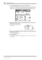
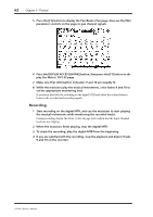
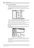
Mixing Recorded Tracks into Stereo (Mixdown) 63 Mixing Recorded Tracks into Stereo (Mixdown) "Mixdown" is the process of mixing recorded tracks into stereo and recording the stereo signal to an external master recorder. This section describes how to mix signals recorded on Tracks 1-16 into a stereo signal, then apply the 01V96's internal effects to the signal, then record it to an external master recorder. Connecting and Setting Up the Master Recorder Follow the steps below to connect a DAT recorder, MD recorder, CD recorder or other master recorder to the 01V96. Change the 01V96's internal patch so that you can monitor the playback signal on the master recorder through ST IN Channel 2. 1 Connect a master recorder to the 01V96. In the following example, the 01V96 2TR OUT DIGITAL connector is connected to the master recorder's digital input, and the 01V96 2TR IN DIGITAL connector is connected to the master recorder's digital output. CH1-4 CH5-8 CH9-12 1 2 3 4 5 6 7 8 9 10 11 12 13 15 PHANTOM +48V A A A A A A A A A A A A 14 B B B B B B B B B B B B INPUT (BAL) INSERT OUT IN (UNBAL) INSERT I/O INSERT I/O INSERT I/O INSERT I/O INSERT I/O INSERT I/O INSERT I/O INSERT I/O INSERT I/O INSERT I/O INSERT I/O INSERT I/O L 16 R IN OUT 2TR -10dBV (UNBAL) PHONES CH15/16 2TR IN MONITOR 2TR IN PAD 20dB -16 -60 GAIN PEAK SIGNAL 20dB -16 -60 GAIN PEAK SIGNAL 20dB -16 -60 GAIN PEAK SIGNAL 20dB -16 -60 GAIN PEAK SIGNAL 20dB -16 -60 GAIN PEAK SIGNAL 20dB -16 -60 GAIN PEAK SIGNAL 20dB -16 -60 GAIN PEAK SIGNAL 20dB -16 -60 GAIN PEAK SIGNAL 20dB -16 -60 GAIN PEAK SIGNAL 20dB -16 -60 GAIN PEAK SIGNAL 20dB -16 -60 GAIN PEAK SIGNAL 20dB +4 GAIN -26 +4 GAIN -26 0 LEVEL10 -16 -60 GAIN +4 GAIN -26 +4 GAIN -26 MONITOR OUT PEAK SIGNAL 13 PEAK SIGNAL 14 15 PEAK SIGNAL 16 0 LEVEL10 PHONES DISPLAY ACCESS SCENE MEMORY SCENE DIO/SETUP MIDI UTILITY / INSERT/ PAN/ PAIR/ DELAY ROUTING GROUP PATCH DYNAMICS EQ EFFECT FADER MODE VIEW AUX 1 AUX 2 AUX 3 AUX 4 AUX 5 AUX 6 AUX 7 AUX 8 HOME (METER) LAYER 1-16 17-32 MASTER REMOTE OVER 0 -3 -6 -9 -12 -15 -18 -24 -30 -36 -48 STEREO STORE SELECTED CHANNEL PAN DEC EQUALIZER Q HIGH HIGH-MID FREQUENCY LOW-MID GAIN LOW ENTER RECALL SOLO CLEAR INC ST IN SEL SEL SEL SEL SEL SEL SEL SEL SEL SEL SEL SEL SEL SEL SEL SEL SOLO SOLO SOLO SOLO SOLO SOLO SOLO SOLO SOLO SOLO SOLO SOLO SOLO SOLO SOLO SOLO ON ON ON ON ON ON ON ON ON ON ON ON ON ON ON ON 1 2 3 4 5 6 7 8 9 10 11 12 13 14 15 16 SEL SEL SEL SOLO SOLO ON ON ON ST IN 1 ST IN 2 +10 0 +10 0 +10 0 +10 0 +10 0 +10 0 +10 0 +10 0 +10 0 +10 0 +10 0 +10 0 +10 0 +10 0 +10 0 +10 00 5 5 5 5 5 5 5 5 5 5 5 5 5 5 5 5 5 5 5 5 5 5 5 5 5 5 5 5 5 5 5 55 0 0 0 0 0 0 0 0 0 0 0 0 0 0 0 0 10 10 10 10 10 10 10 10 10 10 10 10 10 10 10 10 10 5 5 5 5 5 5 5 5 5 5 5 5 5 5 5 5 15 15 15 15 15 15 15 15 15 15 15 15 15 15 15 15 15 10 20 10 20 10 20 10 20 10 20 10 20 10 20 10 20 10 20 10 20 10 20 10 20 10 20 10 20 10 20 10 20 20 15 30 15 30 15 30 15 30 15 30 15 30 15 30 15 30 15 30 15 30 15 30 15 30 15 30 15 30 15 30 15 30 30 20 40 20 40 20 40 20 40 20 40 20 40 20 40 20 40 20 40 20 40 20 40 20 40 20 40 20 40 20 40 20 40 40 30 50 30 50 30 50 30 50 30 50 30 50 30 50 30 50 30 50 30 50 30 50 30 50 30 50 30 50 30 50 30 50 50 40 60 70 40 60 70 40 60 70 40 60 70 40 60 70 40 60 70 40 60 70 40 60 70 40 60 70 40 60 70 40 60 70 40 60 70 40 60 70 40 60 70 40 60 70 40 60 60 70 70 50 50 50 50 50 50 50 50 50 50 50 50 50 50 50 50 USER DEFINED KEYS 1 2 3 4 5 6 7 8 1 17 AUX 1 2 18 AUX 2 3 19 AUX 3 4 20 AUX 4 5 21 AUX 5 6 22 AUX 6 7 23 AUX 7 8 24 AUX 8 9 25 BUS 1 10 26 BUS 2 11 27 BUS 3 12 28 BUS 4 13 29 BUS 5 14 30 BUS 6 15 31 BUS 7 16 32 BUS 8 STEREO 2TR OUT DIGITAL connector 2TR IN DIGITAL connector DIGITAL IN connector DIGITAL OUT connector Master recorder Tutorial 5 Tip: To monitor the master recorder's playback signals, you can also connect the analog output of the master recorder to the 01V96 2TR IN connector. In this way, you can quickly switch the monitoring signal using the Monitor Source selector in the MONITOR OUT section. 2 Press the DISPLAY ACCESS [PATCH] button repeatedly until the Patch | In Patch page appears. 01V96-Owner's Manual
-
 1
1 -
2
-
3
-
4
-
5
-
6
-
7
-
8
-
9
-
10
-
11
-
12
-
13
-
14
-
15
-
16
-
17
-
18
-
19
-
20
-
21
-
22
-
23
-
24
-
25
-
26
-
27
-
28
-
29
-
30
-
31
-
32
-
33
-
34
-
35
-
36
-
37
-
38
-
39
-
40
-
41
-
42
-
43
-
44
-
45
-
46
-
47
-
48
-
49
-
50
-
51
-
52
-
53
-
54
-
55
-
56
-
57
-
 58
58 -
 59
59 -
 60
60 -
 61
61 -
 62
62 -
 63
63 -
 64
64 -
 65
65 -
 66
66 -
 67
67 -
 68
68 -
69
-
70
-
71
-
72
-
73
-
74
-
75
-
76
-
77
-
78
-
79
-
80
-
81
-
82
-
83
-
84
-
85
-
86
-
87
-
88
-
89
-
90
-
91
-
92
-
93
-
94
-
95
-
96
-
97
-
98
-
99
-
100
-
101
-
102
-
103
-
104
-
105
-
106
-
107
-
108
-
109
-
110
-
111
-
112
-
113
-
114
-
115
-
116
-
117
-
118
-
119
-
120
-
121
-
122
-
123
-
124
-
125
-
126
-
127
-
128
-
129
-
130
-
131
-
132
-
133
-
134
-
135
-
136
-
137
-
138
-
139
-
140
-
141
-
142
-
143
-
144
-
145
-
146
-
147
-
148
-
149
-
150
-
151
-
152
-
153
-
154
-
155
-
156
-
157
-
158
-
159
-
160
-
161
-
162
-
163
-
164
-
165
-
166
-
167
-
168
-
169
-
170
-
171
-
172
-
173
-
174
-
175
-
176
-
177
-
178
-
179
-
180
-
181
-
182
-
183
-
184
-
185
-
186
-
187
-
188
-
189
-
190
-
191
-
192
-
193
-
194
-
195
-
196
-
197
-
198
-
199
-
200
-
201
-
202
-
203
-
204
-
205
-
206
-
207
-
208
-
209
-
210
-
211
-
212
-
213
-
214
-
215
-
216
-
217
-
218
-
219
-
220
-
221
-
222
-
223
-
224
-
225
-
226
-
227
-
228
-
229
-
230
-
231
-
232
-
233
-
234
-
235
-
236
-
237
-
238
-
239
-
240
-
241
-
242
-
243
-
244
-
245
-
246
-
247
-
248
-
249
-
250
-
251
-
252
-
253
-
254
-
255
-
256
-
257
-
258
-
259
-
260
-
261
-
262
-
263
-
264
-
265
-
266
-
267
-
268
-
269
-
270
-
271
-
272
-
273
-
274
-
275
-
276
-
277
-
278
-
279
-
280
-
281
-
282
-
283
-
284
-
285
-
286
-
287
-
288
-
289
-
290
-
291
-
292
-
293
-
294
-
295
-
296
-
297
-
298
-
299
-
300
-
301
-
302
-
303
-
304
-
305
-
306
-
307
-
308
-
309
-
310
-
311
-
312
-
313
-
314
-
315
-
316
-
317
-
318
-
319
-
320
-
321
-
322
-
323
-
324
-
325
-
326
-
327
-
328
-
329
-
330
-
331
-
332
-
333
-
334
 |
 |
