Yamaha 01V96 Owner's Manual - Page 109
Aux Outs, Aux Out 1–8
 |
View all Yamaha 01V96 manuals
Add to My Manuals
Save this manual to your list of manuals |
Page 109 highlights
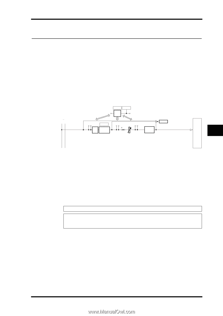
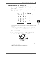
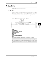
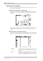
Aux Outs 109 9 Aux Outs This chapter describes how to control Aux Out 1-8. Aux Out 1-8 The Aux Out 1-8 section mixes signals routed from the Input Channels to the corresponding Aux Sends, processes them using on-board EQ, compressor, etc., then routes them to the specified internal effects processors, output connectors or I/O card connectors. The 01V96 features eight Aux Sends, which can be used to send signals to the internal and external effects processors and monitors. The following diagram illustrates the Aux Out 1-8 signal flow. (Gain Reduction) (Out Meter) METER METER COMP INSERT ATT METER 4BAND EQ INSERT ON INSERT LEVEL OUTPUT DELAY METER AUX 1(...8) 9 AUX 1 AUX 8 OUTPUT PATCH Aux Outs • INSERT • ATT (Attenuator) • 4 BAND EQ (4-band equalizer) • COMP (Compressor) • ON (On/Off) • LEVEL • OUTPUT DELAY (Output delay) • METER These parameters are the same as the Stereo Out and Bus Out 1-8 (see page 97). Tip: You can also pair adjacent odd-even Aux Sends (in this order) for stereo Aux operation. Note: With the default setting, Aux Out 1-4 are patched to OMNI OUT connectors 1-4 and to internal Effects processors 1-4. However, you can change this patching on the Patch | Output page. 01V96-Owner's Manual
-
 1
1 -
2
-
3
-
4
-
5
-
6
-
7
-
8
-
9
-
10
-
11
-
12
-
13
-
14
-
15
-
16
-
17
-
18
-
19
-
20
-
21
-
22
-
23
-
24
-
25
-
26
-
27
-
28
-
29
-
30
-
31
-
32
-
33
-
34
-
35
-
36
-
37
-
38
-
39
-
40
-
41
-
42
-
43
-
44
-
45
-
46
-
47
-
48
-
49
-
50
-
51
-
52
-
53
-
54
-
55
-
56
-
57
-
58
-
59
-
60
-
61
-
62
-
63
-
64
-
65
-
66
-
67
-
68
-
69
-
70
-
71
-
72
-
73
-
74
-
75
-
76
-
77
-
78
-
79
-
80
-
81
-
82
-
83
-
84
-
85
-
86
-
87
-
88
-
89
-
90
-
91
-
92
-
93
-
94
-
95
-
96
-
97
-
98
-
99
-
100
-
101
-
102
-
103
-
 104
104 -
 105
105 -
 106
106 -
 107
107 -
 108
108 -
 109
109 -
 110
110 -
 111
111 -
 112
112 -
 113
113 -
 114
114 -
115
-
116
-
117
-
118
-
119
-
120
-
121
-
122
-
123
-
124
-
125
-
126
-
127
-
128
-
129
-
130
-
131
-
132
-
133
-
134
-
135
-
136
-
137
-
138
-
139
-
140
-
141
-
142
-
143
-
144
-
145
-
146
-
147
-
148
-
149
-
150
-
151
-
152
-
153
-
154
-
155
-
156
-
157
-
158
-
159
-
160
-
161
-
162
-
163
-
164
-
165
-
166
-
167
-
168
-
169
-
170
-
171
-
172
-
173
-
174
-
175
-
176
-
177
-
178
-
179
-
180
-
181
-
182
-
183
-
184
-
185
-
186
-
187
-
188
-
189
-
190
-
191
-
192
-
193
-
194
-
195
-
196
-
197
-
198
-
199
-
200
-
201
-
202
-
203
-
204
-
205
-
206
-
207
-
208
-
209
-
210
-
211
-
212
-
213
-
214
-
215
-
216
-
217
-
218
-
219
-
220
-
221
-
222
-
223
-
224
-
225
-
226
-
227
-
228
-
229
-
230
-
231
-
232
-
233
-
234
-
235
-
236
-
237
-
238
-
239
-
240
-
241
-
242
-
243
-
244
-
245
-
246
-
247
-
248
-
249
-
250
-
251
-
252
-
253
-
254
-
255
-
256
-
257
-
258
-
259
-
260
-
261
-
262
-
263
-
264
-
265
-
266
-
267
-
268
-
269
-
270
-
271
-
272
-
273
-
274
-
275
-
276
-
277
-
278
-
279
-
280
-
281
-
282
-
283
-
284
-
285
-
286
-
287
-
288
-
289
-
290
-
291
-
292
-
293
-
294
-
295
-
296
-
297
-
298
-
299
-
300
-
301
-
302
-
303
-
304
-
305
-
306
-
307
-
308
-
309
-
310
-
311
-
312
-
313
-
314
-
315
-
316
-
317
-
318
-
319
-
320
-
321
-
322
-
323
-
324
-
325
-
326
-
327
-
328
-
329
-
330
-
331
-
332
-
333
-
334
 |
 |