Yamaha 01V96 Owner's Manual - Page 98
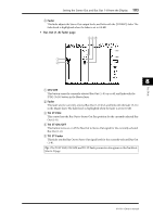
Bus Out 1–8, METER, INSERT, ATT Attenuator, BAND EQ 4-band equalizer, COMP Compressor, ON On/Off
 |
View all Yamaha 01V96 manuals
Add to My Manuals
Save this manual to your list of manuals |
Page 98 highlights
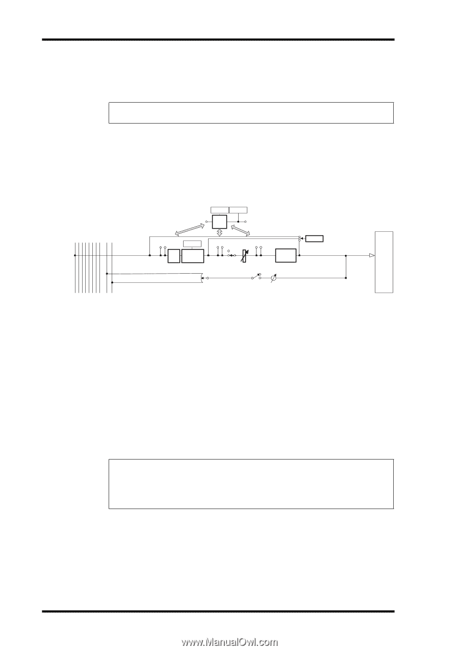
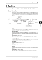
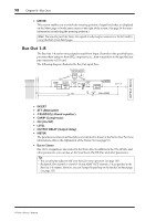
98 Chapter 8-Bus Outs • METER This section enables you to switch the metering position of signal levels that are displayed on the Meter page or by the stereo meter to the right of the screen. (See page 34 for more information on selecting the metering position.) Note: You can also patch the Stereo Out signals to other output connectors or the I/O card by using the Patch | Out Patch pages. Bus Out 1-8 The Bus Out 1-8 section mixes signals routed from Input Channels to the specified buses, processes them using on-board EQ, compressor, etc., then routes them to the specified output connectors or I/O card. The following diagram illustrates the Bus Out signal flow. (Gain Reduction) (Out Meter) METER METER COMP INSERT ATT METER 4BAND EQ INSERT ON INSERT LEVEL OUTPUT DELAY METER ON LEVEL PAN BUS to STEREO BUS 1(...8) BUS1 BUS2 BUS3 BUS4 BUS5 BUS6 BUS7 BUS8 STEREO L STEREO R OUTPUT PATCH • INSERT • ATT (Attenuator) • 4 BAND EQ (4-band equalizer) • COMP (Compressor) • ON (On/Off) • LEVEL • OUTPUT DELAY (Output delay) • METER The parameters and sections listed above are identical to those for the Stereo Out. For more information, refer to the explanation of the Stereo Out (see page 97). • Bus to Stereo Bus Out 1-8 signals are also routed to the Stereo Bus. In addition to the ON, LEVEL, and other parameters, you can also set the Send Level, On/Off, Pan, and other parameters. Tip: • You can also pair adjacent odd-even buses for stereo operation (see page 105). • By default, Slot channels 1-8 and 9-16 and ADAT OUT channels 1-8 are patched to the Bus Out 1-8 outputs. However, you can change this patching on the Patch | Out Patch page (see page 123). 01V96-Owner's Manual
-
 1
1 -
2
-
3
-
4
-
5
-
6
-
7
-
8
-
9
-
10
-
11
-
12
-
13
-
14
-
15
-
16
-
17
-
18
-
19
-
20
-
21
-
22
-
23
-
24
-
25
-
26
-
27
-
28
-
29
-
30
-
31
-
32
-
33
-
34
-
35
-
36
-
37
-
38
-
39
-
40
-
41
-
42
-
43
-
44
-
45
-
46
-
47
-
48
-
49
-
50
-
51
-
52
-
53
-
54
-
55
-
56
-
57
-
58
-
59
-
60
-
61
-
62
-
63
-
64
-
65
-
66
-
67
-
68
-
69
-
70
-
71
-
72
-
73
-
74
-
75
-
76
-
77
-
78
-
79
-
80
-
81
-
82
-
83
-
84
-
85
-
86
-
87
-
88
-
89
-
90
-
91
-
92
-
 93
93 -
 94
94 -
 95
95 -
 96
96 -
 97
97 -
 98
98 -
 99
99 -
 100
100 -
 101
101 -
 102
102 -
 103
103 -
104
-
105
-
106
-
107
-
108
-
109
-
110
-
111
-
112
-
113
-
114
-
115
-
116
-
117
-
118
-
119
-
120
-
121
-
122
-
123
-
124
-
125
-
126
-
127
-
128
-
129
-
130
-
131
-
132
-
133
-
134
-
135
-
136
-
137
-
138
-
139
-
140
-
141
-
142
-
143
-
144
-
145
-
146
-
147
-
148
-
149
-
150
-
151
-
152
-
153
-
154
-
155
-
156
-
157
-
158
-
159
-
160
-
161
-
162
-
163
-
164
-
165
-
166
-
167
-
168
-
169
-
170
-
171
-
172
-
173
-
174
-
175
-
176
-
177
-
178
-
179
-
180
-
181
-
182
-
183
-
184
-
185
-
186
-
187
-
188
-
189
-
190
-
191
-
192
-
193
-
194
-
195
-
196
-
197
-
198
-
199
-
200
-
201
-
202
-
203
-
204
-
205
-
206
-
207
-
208
-
209
-
210
-
211
-
212
-
213
-
214
-
215
-
216
-
217
-
218
-
219
-
220
-
221
-
222
-
223
-
224
-
225
-
226
-
227
-
228
-
229
-
230
-
231
-
232
-
233
-
234
-
235
-
236
-
237
-
238
-
239
-
240
-
241
-
242
-
243
-
244
-
245
-
246
-
247
-
248
-
249
-
250
-
251
-
252
-
253
-
254
-
255
-
256
-
257
-
258
-
259
-
260
-
261
-
262
-
263
-
264
-
265
-
266
-
267
-
268
-
269
-
270
-
271
-
272
-
273
-
274
-
275
-
276
-
277
-
278
-
279
-
280
-
281
-
282
-
283
-
284
-
285
-
286
-
287
-
288
-
289
-
290
-
291
-
292
-
293
-
294
-
295
-
296
-
297
-
298
-
299
-
300
-
301
-
302
-
303
-
304
-
305
-
306
-
307
-
308
-
309
-
310
-
311
-
312
-
313
-
314
-
315
-
316
-
317
-
318
-
319
-
320
-
321
-
322
-
323
-
324
-
325
-
326
-
327
-
328
-
329
-
330
-
331
-
332
-
333
-
334
 |
 |