Yamaha 01V96 Owner's Manual - Page 39
Configuring a recording system that uses a DAW Digital Audio, Workstation, installed in the slot
 |
View all Yamaha 01V96 manuals
Add to My Manuals
Save this manual to your list of manuals |
Page 39 highlights
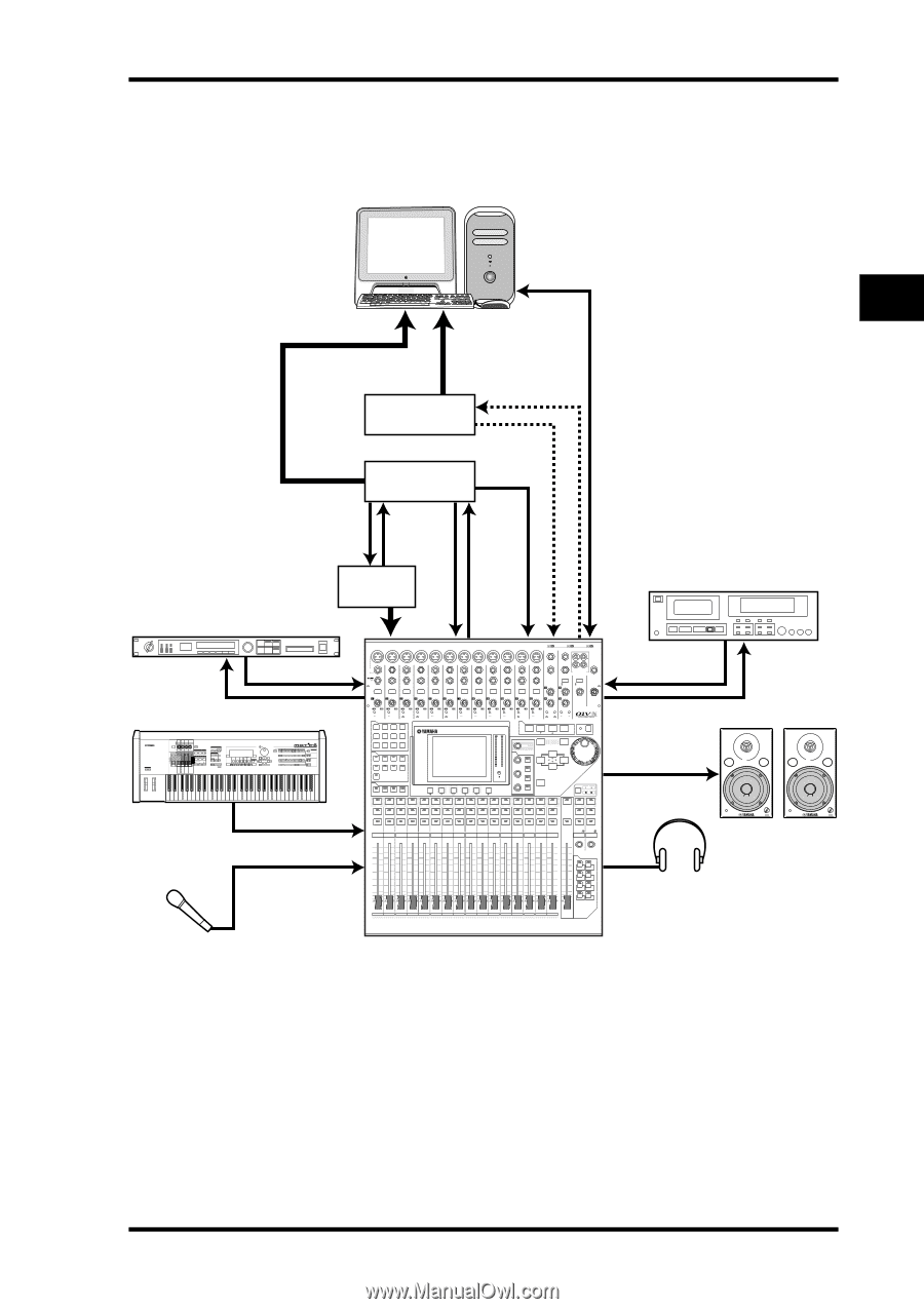
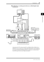
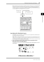
Connections 39 ■ Configuring a recording system that uses a DAW (Digital Audio Workstation) Computer 4 Connections and Setup MIDI interface MIDI IN MIDI OUT Audio interface WORD CLOCK OUT OUT IN OUT IN ADAT IN ADAT OUT WORD CLOCK IN connector MIDI IN MIDI OUT TO HOST USB port MY-16AT etc. Master recorder Effects processor 88 Synthesizer REC SONG SCENE SLOT INPUT connector OMNI OUT connector CH1-4 CH5-8 CH9-12 1 2 3 4 5 6 7 8 9 10 11 12 13 15 PHANTOM +48V A A A A A A A A A A A A 14 B B B B B B B B B B B B INPUT (BAL) INSERT OUT IN (UNBAL) INSERT I/O INSERT I/O INSERT I/O INSERT I/O INSERT I/O INSERT I/O INSERT I/O INSERT I/O INSERT I/O INSERT I/O INSERT I/O INSERT I/O L 16 R IN OUT 2TR -10dBV (UNBAL) PHONES CH15/16 2TR IN MONITOR 2TR IN PAD 20dB -16 -60 GAIN PEAK SIGNAL 20dB -16 -60 GAIN PEAK SIGNAL 20dB -16 -60 GAIN PEAK SIGNAL 20dB -16 -60 GAIN PEAK SIGNAL 20dB -16 -60 GAIN PEAK SIGNAL 20dB -16 -60 GAIN PEAK SIGNAL 20dB -16 -60 GAIN PEAK SIGNAL 20dB -16 -60 GAIN PEAK SIGNAL 20dB -16 -60 GAIN PEAK SIGNAL 20dB -16 -60 GAIN PEAK SIGNAL 20dB -16 -60 GAIN PEAK SIGNAL 20dB +4 GAIN -26 +4 GAIN -26 0 10 LEVEL -16 -60 GAIN +4 GAIN -26 +4 GAIN -26 MONITOR OUT PEAK SIGNAL 13 PEAK SIGNAL 14 15 PEAK SIGNAL 16 0 10 LEVEL PHONES DISPLAY ACCESS SCENE MEMORY MUSIC PRODUCTION SYNTHESIZER Integrated Sampling Sequencer Real-time External Control Surface Modular Synthesis Plug-in System SCENE DIO/SETUP MIDI UTILITY / INSERT/ PAN/ PAIR/ DELAY ROUTING GROUP PATCH DYNAMICS EQ EFFECT FADER MODE VIEW AUX 1 AUX 2 AUX 3 AUX 4 AUX 5 AUX 6 AUX 7 AUX 8 HOME (METER) LAYER 1-16 17-32 MASTER REMOTE OVER 0 -3 -6 -9 -12 -15 -18 -24 -30 -36 -48 STEREO STORE SELECTED CHANNEL PAN DEC EQUALIZER Q HIGH HIGH-MID FREQUENCY LOW-MID GAIN LOW ENTER RECALL SOLO CLEAR INC ST IN INPUT connector SEL SEL SEL SEL SEL SEL SEL SEL SEL SEL SEL SEL SEL SEL SEL SEL SOLO SOLO SOLO SOLO SOLO SOLO SOLO SOLO SOLO SOLO SOLO SOLO SOLO SOLO SOLO SOLO ON ON ON ON ON ON ON ON ON ON ON ON ON ON ON ON 1 2 3 4 5 6 7 8 9 10 11 12 13 14 15 16 SEL SEL SEL SOLO SOLO ON ON ON ST IN 1 ST IN 2 2TR IN connector 2TR OUT connector MONITOR OUT connectors INPUT connector +10 0 +10 0 +10 0 +10 0 +10 0 +10 0 +10 0 +10 0 +10 0 +10 0 +10 0 +10 0 +10 0 +10 0 +10 0 +10 00 5 5 5 5 5 5 5 5 5 5 5 5 5 5 5 5 5 5 5 5 5 5 5 5 5 5 5 5 5 5 5 55 0 0 0 0 0 0 0 0 0 0 0 0 0 0 0 0 10 10 10 10 10 10 10 10 10 10 10 10 10 10 10 10 10 5 5 5 5 5 5 5 5 5 5 5 5 5 5 5 5 15 15 15 15 15 15 15 15 15 15 15 15 15 15 15 15 15 10 20 10 20 10 20 10 20 10 20 10 20 10 20 10 20 10 20 10 20 10 20 10 20 10 20 10 20 10 20 10 20 20 15 30 15 30 15 30 15 30 15 30 15 30 15 30 15 30 15 30 15 30 15 30 15 30 15 30 15 30 15 30 15 30 30 20 40 20 40 20 40 20 40 20 40 20 40 20 40 20 40 20 40 20 40 20 40 20 40 20 40 20 40 20 40 20 40 40 30 50 30 50 30 50 30 50 30 50 30 50 30 50 30 50 30 50 30 50 30 50 30 50 30 50 30 50 30 50 30 50 50 40 60 70 40 60 70 40 60 70 40 60 70 40 60 70 40 60 70 40 60 70 40 60 70 40 60 70 40 60 70 40 60 70 40 60 70 40 60 70 40 60 70 40 60 70 40 60 60 70 70 50 50 50 50 50 50 50 50 50 50 50 50 50 50 50 50 USER DEFINED KEYS 1 2 3 4 5 6 7 8 1 17 AUX 1 2 18 AUX 2 3 19 AUX 3 4 20 AUX 4 5 21 AUX 5 6 22 AUX 6 7 23 AUX 7 8 24 AUX 8 9 25 BUS 1 10 26 BUS 2 11 27 BUS 3 12 28 BUS 4 13 29 BUS 5 14 30 BUS 6 15 31 BUS 7 16 32 BUS 8 STEREO PHONES jack VOL VOL Monitoring system In this system, the 01V96, with an optional I/O card (MY8-AT, MY16-AT, MY8-AE, etc.) installed in the slot, is connected to a computer-based DAW (Digital Audio Workstation). The 01V96 can provide audio input and output for the DAW. If you connect the 01V96 and the computer via USB, the 01V96's Remote function enables you to control the DAW's locate and transport functions and change the parameters. 01V96-Owner's Manual
-
 1
1 -
2
-
3
-
4
-
5
-
6
-
7
-
8
-
9
-
10
-
11
-
12
-
13
-
14
-
15
-
16
-
17
-
18
-
19
-
20
-
21
-
22
-
23
-
24
-
25
-
26
-
27
-
28
-
29
-
30
-
31
-
32
-
33
-
 34
34 -
 35
35 -
 36
36 -
 37
37 -
 38
38 -
 39
39 -
 40
40 -
 41
41 -
 42
42 -
 43
43 -
 44
44 -
45
-
46
-
47
-
48
-
49
-
50
-
51
-
52
-
53
-
54
-
55
-
56
-
57
-
58
-
59
-
60
-
61
-
62
-
63
-
64
-
65
-
66
-
67
-
68
-
69
-
70
-
71
-
72
-
73
-
74
-
75
-
76
-
77
-
78
-
79
-
80
-
81
-
82
-
83
-
84
-
85
-
86
-
87
-
88
-
89
-
90
-
91
-
92
-
93
-
94
-
95
-
96
-
97
-
98
-
99
-
100
-
101
-
102
-
103
-
104
-
105
-
106
-
107
-
108
-
109
-
110
-
111
-
112
-
113
-
114
-
115
-
116
-
117
-
118
-
119
-
120
-
121
-
122
-
123
-
124
-
125
-
126
-
127
-
128
-
129
-
130
-
131
-
132
-
133
-
134
-
135
-
136
-
137
-
138
-
139
-
140
-
141
-
142
-
143
-
144
-
145
-
146
-
147
-
148
-
149
-
150
-
151
-
152
-
153
-
154
-
155
-
156
-
157
-
158
-
159
-
160
-
161
-
162
-
163
-
164
-
165
-
166
-
167
-
168
-
169
-
170
-
171
-
172
-
173
-
174
-
175
-
176
-
177
-
178
-
179
-
180
-
181
-
182
-
183
-
184
-
185
-
186
-
187
-
188
-
189
-
190
-
191
-
192
-
193
-
194
-
195
-
196
-
197
-
198
-
199
-
200
-
201
-
202
-
203
-
204
-
205
-
206
-
207
-
208
-
209
-
210
-
211
-
212
-
213
-
214
-
215
-
216
-
217
-
218
-
219
-
220
-
221
-
222
-
223
-
224
-
225
-
226
-
227
-
228
-
229
-
230
-
231
-
232
-
233
-
234
-
235
-
236
-
237
-
238
-
239
-
240
-
241
-
242
-
243
-
244
-
245
-
246
-
247
-
248
-
249
-
250
-
251
-
252
-
253
-
254
-
255
-
256
-
257
-
258
-
259
-
260
-
261
-
262
-
263
-
264
-
265
-
266
-
267
-
268
-
269
-
270
-
271
-
272
-
273
-
274
-
275
-
276
-
277
-
278
-
279
-
280
-
281
-
282
-
283
-
284
-
285
-
286
-
287
-
288
-
289
-
290
-
291
-
292
-
293
-
294
-
295
-
296
-
297
-
298
-
299
-
300
-
301
-
302
-
303
-
304
-
305
-
306
-
307
-
308
-
309
-
310
-
311
-
312
-
313
-
314
-
315
-
316
-
317
-
318
-
319
-
320
-
321
-
322
-
323
-
324
-
325
-
326
-
327
-
328
-
329
-
330
-
331
-
332
-
333
-
334
 |
 |