Yamaha 01V96 Owner's Manual - Page 53
To route Input Channel signals to Direct Outs, press the DISPLAY ACCESS
 |
View all Yamaha 01V96 manuals
Add to My Manuals
Save this manual to your list of manuals |
Page 53 highlights
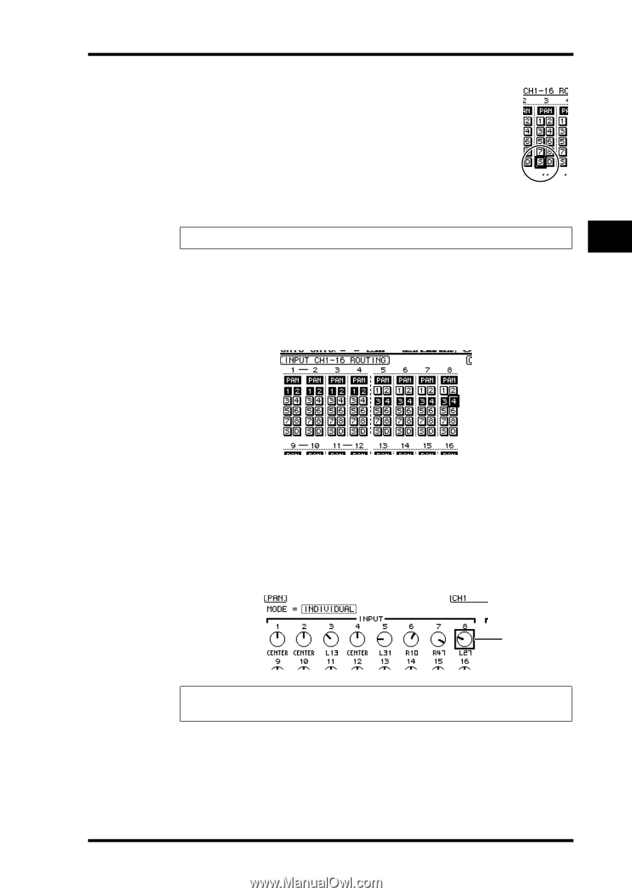
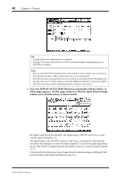
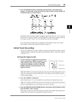
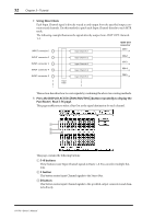
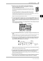
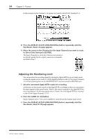
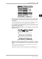
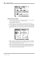
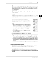
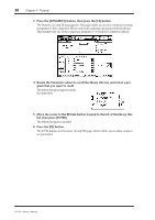
Initial Track Recording 53 2 Move the cursor to the S button for the Input Channel to which the musical instrument or microphone is connected, then press [ENTER] to turn it off. By default, each Input Channel is routed to the Stereo Bus, which enables you to monitor the signals from the MONITOR OUT connectors and the PHONES jack. However, during multitrack recording you may usually want to monitor the signals returned from the connected digital MTR, rather than monitoring the Input Channel signals. To do so, you must turn off the S button so that the particular Input Channel signals will not be routed to the Stereo Bus. Tip: The S buttons for paired channels are linked. 5 Tutorial 3 To route Input Channel signals to the connected digital MTR via Buses 1-8, use the 1-8 buttons to specify a Bus Out as the destination for each of the Input Channels to which the musical instruments and microphone are connected. In this example, Input Channels 1-4 are assigned to Buses 1 and 2, and Input Channels 5-8 are assigned to Buses 3 and 4. 4 Press the [PAN/ROUTING] button repeatedly to display the Pan/Route | Pan page. This page enables you to set the panpots for signals routed from the Input Channels to the Stereo Bus, and for signals routed from the Input Channels to the odd-even buses. 5 Move the cursor to the PAN parameter controls for the Input Channels that are assigned to the odd-even buses, then rotate the Parameter wheel or press the [INC]/[DEC] buttons to set the pan. Cursor on the PAN parameter control Tip: You can also use the [SEL] buttons to select Input Channels, and the SELECTED CHANNEL [PAN] control to adjust the pan setting. 6 To route Input Channel signals to Direct Outs, press the DISPLAY ACCESS [PATCH] button repeatedly until the Patch | Direct Out page appears. The Direct Out page enables you to specify the output connectors or channels to which each Input Channel is directly patched. 7 Move the cursor to the parameter box for the Input Channels you want to route to Direct Outs, then specify the output connectors or channels. 01V96-Owner's Manual
-
 1
1 -
2
-
3
-
4
-
5
-
6
-
7
-
8
-
9
-
10
-
11
-
12
-
13
-
14
-
15
-
16
-
17
-
18
-
19
-
20
-
21
-
22
-
23
-
24
-
25
-
26
-
27
-
28
-
29
-
30
-
31
-
32
-
33
-
34
-
35
-
36
-
37
-
38
-
39
-
40
-
41
-
42
-
43
-
44
-
45
-
46
-
47
-
 48
48 -
 49
49 -
 50
50 -
 51
51 -
 52
52 -
 53
53 -
 54
54 -
 55
55 -
 56
56 -
 57
57 -
 58
58 -
59
-
60
-
61
-
62
-
63
-
64
-
65
-
66
-
67
-
68
-
69
-
70
-
71
-
72
-
73
-
74
-
75
-
76
-
77
-
78
-
79
-
80
-
81
-
82
-
83
-
84
-
85
-
86
-
87
-
88
-
89
-
90
-
91
-
92
-
93
-
94
-
95
-
96
-
97
-
98
-
99
-
100
-
101
-
102
-
103
-
104
-
105
-
106
-
107
-
108
-
109
-
110
-
111
-
112
-
113
-
114
-
115
-
116
-
117
-
118
-
119
-
120
-
121
-
122
-
123
-
124
-
125
-
126
-
127
-
128
-
129
-
130
-
131
-
132
-
133
-
134
-
135
-
136
-
137
-
138
-
139
-
140
-
141
-
142
-
143
-
144
-
145
-
146
-
147
-
148
-
149
-
150
-
151
-
152
-
153
-
154
-
155
-
156
-
157
-
158
-
159
-
160
-
161
-
162
-
163
-
164
-
165
-
166
-
167
-
168
-
169
-
170
-
171
-
172
-
173
-
174
-
175
-
176
-
177
-
178
-
179
-
180
-
181
-
182
-
183
-
184
-
185
-
186
-
187
-
188
-
189
-
190
-
191
-
192
-
193
-
194
-
195
-
196
-
197
-
198
-
199
-
200
-
201
-
202
-
203
-
204
-
205
-
206
-
207
-
208
-
209
-
210
-
211
-
212
-
213
-
214
-
215
-
216
-
217
-
218
-
219
-
220
-
221
-
222
-
223
-
224
-
225
-
226
-
227
-
228
-
229
-
230
-
231
-
232
-
233
-
234
-
235
-
236
-
237
-
238
-
239
-
240
-
241
-
242
-
243
-
244
-
245
-
246
-
247
-
248
-
249
-
250
-
251
-
252
-
253
-
254
-
255
-
256
-
257
-
258
-
259
-
260
-
261
-
262
-
263
-
264
-
265
-
266
-
267
-
268
-
269
-
270
-
271
-
272
-
273
-
274
-
275
-
276
-
277
-
278
-
279
-
280
-
281
-
282
-
283
-
284
-
285
-
286
-
287
-
288
-
289
-
290
-
291
-
292
-
293
-
294
-
295
-
296
-
297
-
298
-
299
-
300
-
301
-
302
-
303
-
304
-
305
-
306
-
307
-
308
-
309
-
310
-
311
-
312
-
313
-
314
-
315
-
316
-
317
-
318
-
319
-
320
-
321
-
322
-
323
-
324
-
325
-
326
-
327
-
328
-
329
-
330
-
331
-
332
-
333
-
334
 |
 |