Kyocera KM-5530 KM/Ri 4530/5530 Operation Guide Rev 5F - Page 215
touch the Scanning finished key. Copying will start
 |
View all Kyocera KM-5530 manuals
Add to My Manuals
Save this manual to your list of manuals |
Page 215 highlights
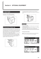
Section 8 OPTIONAL EQUIPMENT * The hole punching position will be displayed on the image of the finished copies that appears in the touch panel, as shown in the illustration below. Verify the number and position of the holes before copying. When the combination of the selected functions does not allow hole punching, the hole marks will not appear on the displayed image. Inch specifications Orientation of originals No and position. of holes 2 holes Left side 2 holes Right side 2 holes Top 3 holes Left side 3 holes Right side 3 holes Top Punching Not possible Metric specifications Orientation of originals No and position. of holes 2 holes Left side 2 holes Right side 2 holes Top 4 holes Left side 4 holes Right side 4 holes Top Punching Not possible IMPORTANT! The position of the holes on each page may differ very slightly. This may be especially true if the automatic drawer[cassette] switching function engages and changes to paper feed from a different drawer[cassette]. 4 Set the originals to be copied. Verify the direction in which the originals were set. 5 Press the [Start] key. Scanning of the originals will start and the number of originals that was set will be displayed. NOTE If you do not set the originals in the Document Processor, perform the appropriate procedure to set all of the originals to be copied. 6 Once all of the originals have been completely scanned, touch the "Scanning finished" key. Copying will start and each finished copy will be automatically hole punched and ejected onto the Finisher. 7 Once copying is completed, removed the finished copies from the Finisher. 8-5
-
 1
1 -
2
-
3
-
4
-
5
-
6
-
7
-
8
-
9
-
10
-
11
-
12
-
13
-
14
-
15
-
16
-
17
-
18
-
19
-
20
-
21
-
22
-
23
-
24
-
25
-
26
-
27
-
28
-
29
-
30
-
31
-
32
-
33
-
34
-
35
-
36
-
37
-
38
-
39
-
40
-
41
-
42
-
43
-
44
-
45
-
46
-
47
-
48
-
49
-
50
-
51
-
52
-
53
-
54
-
55
-
56
-
57
-
58
-
59
-
60
-
61
-
62
-
63
-
64
-
65
-
66
-
67
-
68
-
69
-
70
-
71
-
72
-
73
-
74
-
75
-
76
-
77
-
78
-
79
-
80
-
81
-
82
-
83
-
84
-
85
-
86
-
87
-
88
-
89
-
90
-
91
-
92
-
93
-
94
-
95
-
96
-
97
-
98
-
99
-
100
-
101
-
102
-
103
-
104
-
105
-
106
-
107
-
108
-
109
-
110
-
111
-
112
-
113
-
114
-
115
-
116
-
117
-
118
-
119
-
120
-
121
-
122
-
123
-
124
-
125
-
126
-
127
-
128
-
129
-
130
-
131
-
132
-
133
-
134
-
135
-
136
-
137
-
138
-
139
-
140
-
141
-
142
-
143
-
144
-
145
-
146
-
147
-
148
-
149
-
150
-
151
-
152
-
153
-
154
-
155
-
156
-
157
-
158
-
159
-
160
-
161
-
162
-
163
-
164
-
165
-
166
-
167
-
168
-
169
-
170
-
171
-
172
-
173
-
174
-
175
-
176
-
177
-
178
-
179
-
180
-
181
-
182
-
183
-
184
-
185
-
186
-
187
-
188
-
189
-
190
-
191
-
192
-
193
-
194
-
195
-
196
-
197
-
198
-
199
-
200
-
201
-
202
-
203
-
204
-
205
-
206
-
207
-
208
-
209
-
 210
210 -
 211
211 -
 212
212 -
 213
213 -
 214
214 -
 215
215 -
 216
216 -
 217
217 -
 218
218 -
 219
219 -
 220
220 -
221
-
222
-
223
-
224
-
225
-
226
-
227
-
228
-
229
-
230
-
231
-
232
-
233
-
234
-
235
-
236
-
237
-
238
-
239
-
240
-
241
-
242
-
243
-
244
-
245
-
246
-
247
-
248
-
249
-
250
-
251
-
252
 |
 |
