Canon XF605 Instruction Manual - Page 18
SDI OUT terminal, USB Type-C terminal
 |
View all Canon XF605 manuals
Add to My Manuals
Save this manual to your list of manuals |
Page 18 highlights
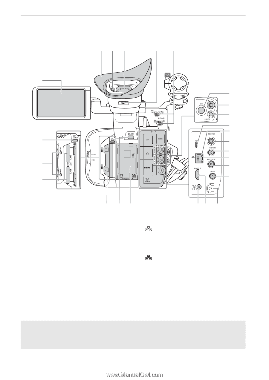
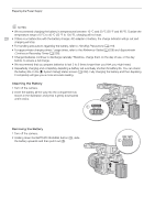
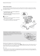
Names of Parts 18 1 2 3 4 56 7 8 9 10 11 12 13 14 15 16 17 18 19 20 21 22 23 24 25 1 LCD monitor with touch screen (A 23) 2 SLOT SELECT (SD card selection) button (A 33) 3 SD card access indicators (SD2/SD3) (A 32) 4 SD card slots (A 32): SD CARD2 (top) and SD CARD3 (bottom) In this manual, SD cards in each slot are referred to as "SD card A" and "SD card B", respectively. 5 Eye cup (A 30) 6 Eye sensor (A 29) 7 Viewfinder (A 29) 8 Dioptric adjustment lever (A 29) 9 INPUT 1/INPUT 2 (audio input selection) switch (A 94) 10 REC (start/stop recording) button (A 41) 11 Joystick (A 25) Can be pushed in 4 directions. You can also push the joystick itself to confirm a selection. 12 CANCEL button (A 25) 13 USB (Type-C) terminal (A 113, 155) 14 (Ethernet) indicator (A 159) 15 REMOTE B terminal For connecting the optional RC-V100 Remote Controller (A 111). 16 TIME CODE terminal (A 88) 17 (Ethernet) terminal (A 159) 18 G-LOCK/SYNC terminal (A 89) 19 SDI OUT terminal (A 139, 144) 20 Card compartment covers (A 32) 21 BATTERY RELEASE button (A 20) 22 Battery compartment (A 20) 23 DC IN terminal (A 22) 24 HDMI OUT terminal (A 139, 145) 25 DC cable clamp (A 22) Removing and attaching the terminal covers You can remove the covers of the camera's terminals to access them more easily. To remove a terminal's cover, open the cover and gently pull it straight out. To attach back the terminal cover, insert the connecting strip into the opening. If the connecting strip is difficult to grasp, use a pair of tweezers or similar tool.
-
 1
1 -
2
-
3
-
4
-
5
-
6
-
7
-
8
-
9
-
10
-
11
-
12
-
 13
13 -
 14
14 -
 15
15 -
 16
16 -
 17
17 -
 18
18 -
 19
19 -
 20
20 -
 21
21 -
 22
22 -
 23
23 -
24
-
25
-
26
-
27
-
28
-
29
-
30
-
31
-
32
-
33
-
34
-
35
-
36
-
37
-
38
-
39
-
40
-
41
-
42
-
43
-
44
-
45
-
46
-
47
-
48
-
49
-
50
-
51
-
52
-
53
-
54
-
55
-
56
-
57
-
58
-
59
-
60
-
61
-
62
-
63
-
64
-
65
-
66
-
67
-
68
-
69
-
70
-
71
-
72
-
73
-
74
-
75
-
76
-
77
-
78
-
79
-
80
-
81
-
82
-
83
-
84
-
85
-
86
-
87
-
88
-
89
-
90
-
91
-
92
-
93
-
94
-
95
-
96
-
97
-
98
-
99
-
100
-
101
-
102
-
103
-
104
-
105
-
106
-
107
-
108
-
109
-
110
-
111
-
112
-
113
-
114
-
115
-
116
-
117
-
118
-
119
-
120
-
121
-
122
-
123
-
124
-
125
-
126
-
127
-
128
-
129
-
130
-
131
-
132
-
133
-
134
-
135
-
136
-
137
-
138
-
139
-
140
-
141
-
142
-
143
-
144
-
145
-
146
-
147
-
148
-
149
-
150
-
151
-
152
-
153
-
154
-
155
-
156
-
157
-
158
-
159
-
160
-
161
-
162
-
163
-
164
-
165
-
166
-
167
-
168
-
169
-
170
-
171
-
172
-
173
-
174
-
175
-
176
-
177
-
178
-
179
-
180
-
181
-
182
-
183
-
184
-
185
-
186
-
187
-
188
-
189
-
190
-
191
-
192
-
193
-
194
-
195
-
196
-
197
-
198
-
199
-
200
-
201
-
202
-
203
-
204
-
205
-
206
-
207
-
208
-
209
-
210
-
211
-
212
-
213
-
214
-
215
-
216
-
217
-
218
-
219
-
220
-
221
-
222
-
223
-
224
-
225
-
226
-
227
-
228
-
229
-
230
-
231
-
232
-
233
-
234
-
235
-
236
-
237
-
238
 |
 |