Canon XF605 Instruction Manual - Page 89
Time Code Signal Output, Reference Video Signal Input (Genlock Synchronization)
 |
View all Canon XF605 manuals
Add to My Manuals
Save this manual to your list of manuals |
Page 89 highlights
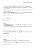
Synchronizing with an External Device • When a suitable external time code signal is received, the camera's own time code will be synchronized to it and the synchronization will be maintained even if you disconnect the cable from the TIME CODE terminal. • If the external time code signal is incorrect or there is no input signal, the internal time code set in the camera will be recorded instead. • When an external time code signal is received, the DF/NDF selection will follow the external time code signal's 89 settings. • If an external time code signal is input while pre-recording is activated, there might be a discontinuity in the time code of the pre-recorded clip. • Performing any of the following actions while the cable is not connected will cause the synchronization to be disrupted; the correct time code will be restored once you reconnect the cable. - Turning the camera on/off - Switching to MEDIA mode - Changing the video configuration Time Code Signal Output The time code signal output from the TIME CODE terminal will be a SMPTE-standard LTC timing signal. The user bit will also be output. Select > [B System Setup] > [TC In/Out] > [Out]. NOTES • About the user bit output: The user bit set by the user (A 87) will be output. In MEDIA mode, the user bit is not output from the TIME CODE terminal. • The time code and user bit will not be output when slow & fast motion recording, frame recording or interval recording are activated. Reference Video Signal Input (Genlock Synchronization) When a reference sync signal (analog blackburst or tri-level signal) is input through the G-LOCK/SYNC terminal, the phases of the camera's V and H sync will automatically be synchronized to it. The phase difference between the external Genlock signal and the camera is initially set to 0. The H phase can be adjusted within the range of approximately ±0.4 H. 1 Select > [B System Setup] > [G-LOCK/SYNC Term.] > [Genlock Input]. 2 Select > [B System Setup] > [Genlock Adjustment] > [Change]. • To reset the adjustment value to [000], select [Reset] instead. 3 Enter the H-phase adjustment value using the data entry screen (A 27). NOTES • When a suitable Genlock signal is input, the Genlock synchronization stabilizes after approximately 10 seconds. • When a suitable Genlock signal is detected, the U icon will flash at the top right of the screen. When the camera locks on the external Genlock signal, the icon will stay on. • If the external Genlock signal is incorrect, the synchronization may not be stable. In such case, the recorded time code may be incorrect.
-
 1
1 -
2
-
3
-
4
-
5
-
6
-
7
-
8
-
9
-
10
-
11
-
12
-
13
-
14
-
15
-
16
-
17
-
18
-
19
-
20
-
21
-
22
-
23
-
24
-
25
-
26
-
27
-
28
-
29
-
30
-
31
-
32
-
33
-
34
-
35
-
36
-
37
-
38
-
39
-
40
-
41
-
42
-
43
-
44
-
45
-
46
-
47
-
48
-
49
-
50
-
51
-
52
-
53
-
54
-
55
-
56
-
57
-
58
-
59
-
60
-
61
-
62
-
63
-
64
-
65
-
66
-
67
-
68
-
69
-
70
-
71
-
72
-
73
-
74
-
75
-
76
-
77
-
78
-
79
-
80
-
81
-
82
-
83
-
 84
84 -
 85
85 -
 86
86 -
 87
87 -
 88
88 -
 89
89 -
 90
90 -
 91
91 -
 92
92 -
 93
93 -
 94
94 -
95
-
96
-
97
-
98
-
99
-
100
-
101
-
102
-
103
-
104
-
105
-
106
-
107
-
108
-
109
-
110
-
111
-
112
-
113
-
114
-
115
-
116
-
117
-
118
-
119
-
120
-
121
-
122
-
123
-
124
-
125
-
126
-
127
-
128
-
129
-
130
-
131
-
132
-
133
-
134
-
135
-
136
-
137
-
138
-
139
-
140
-
141
-
142
-
143
-
144
-
145
-
146
-
147
-
148
-
149
-
150
-
151
-
152
-
153
-
154
-
155
-
156
-
157
-
158
-
159
-
160
-
161
-
162
-
163
-
164
-
165
-
166
-
167
-
168
-
169
-
170
-
171
-
172
-
173
-
174
-
175
-
176
-
177
-
178
-
179
-
180
-
181
-
182
-
183
-
184
-
185
-
186
-
187
-
188
-
189
-
190
-
191
-
192
-
193
-
194
-
195
-
196
-
197
-
198
-
199
-
200
-
201
-
202
-
203
-
204
-
205
-
206
-
207
-
208
-
209
-
210
-
211
-
212
-
213
-
214
-
215
-
216
-
217
-
218
-
219
-
220
-
221
-
222
-
223
-
224
-
225
-
226
-
227
-
228
-
229
-
230
-
231
-
232
-
233
-
234
-
235
-
236
-
237
-
238
 |
 |