Canon XF605 Instruction Manual - Page 82
Onscreen Markers, Zebra Patterns and False Color, Displaying Onscreen Markers, playing
 |
View all Canon XF605 manuals
Add to My Manuals
Save this manual to your list of manuals |
Page 82 highlights
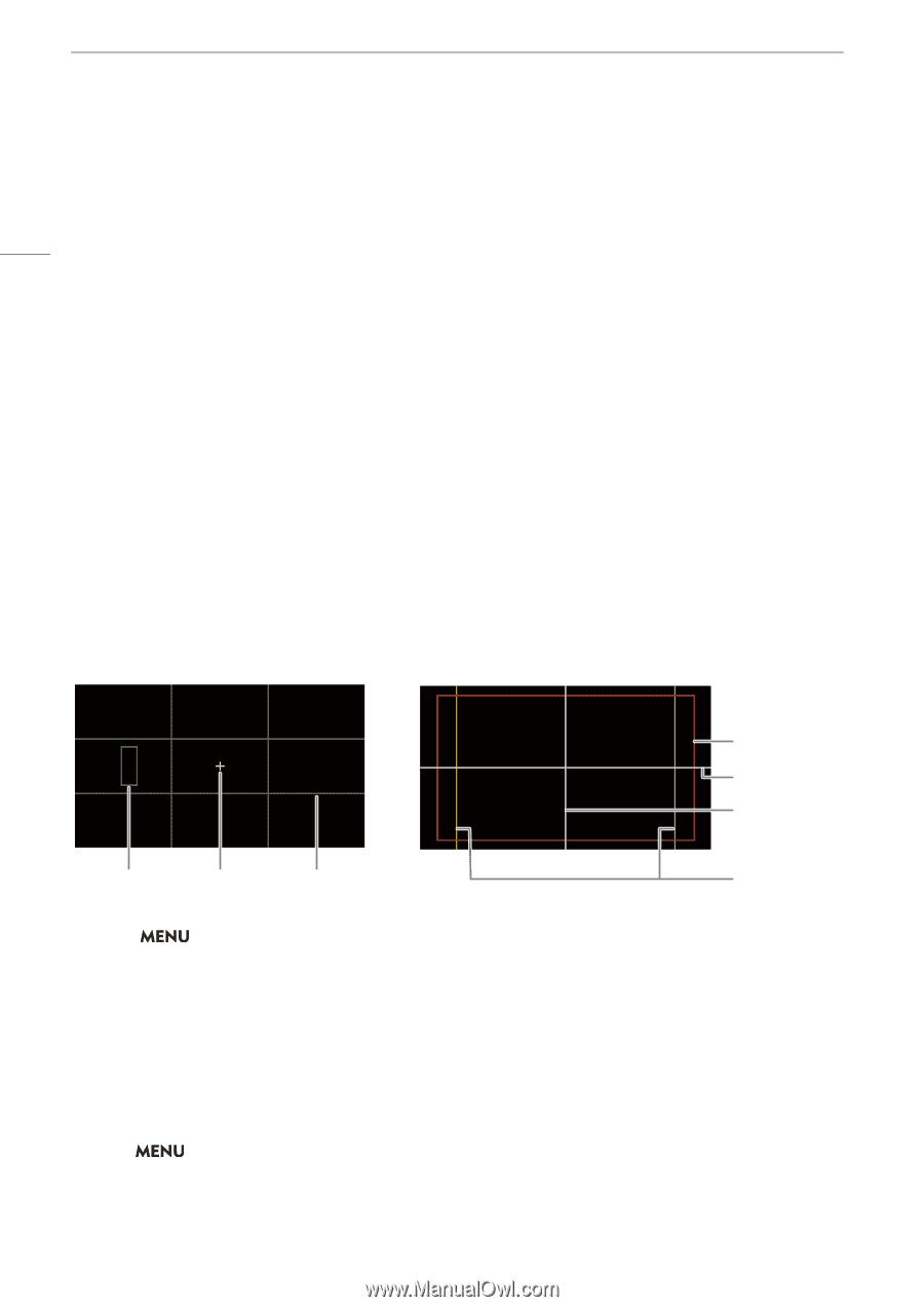
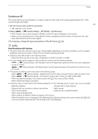
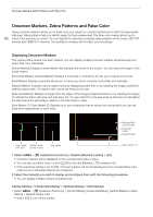
Onscreen Markers, Zebra Patterns and False Color Onscreen Markers, Zebra Patterns and False Color Using onscreen markers allows you to make sure your subject is correctly framed and is within the appropriate safe area. Zebra patterns help you identify areas that are overexposed. The false color overlay allows you to 82 check if the exposure is correct. You can display the assistance overlays independently on the screen, SDI OUT terminal and HDMI OUT terminal. The assistance overlays will not affect your recordings. Displaying Onscreen Markers The camera offers several onscreen markers. You can display multiple onscreen markers simultaneously and select their color individually. [Center Marker]: Displays a small marker that indicates the center of the screen. You can select the shape of the center marker. [Horizontal Marker], [Vertical Marker]: Displays a horizontal or vertical line to help you compose level shots. [Grid Marker]: Displays a grid that allows you to frame your shots correctly (horizontally and vertically). [Aspect Marker]: Indicates various aspect ratios by displaying border lines or by masking the image outside the selected aspect ratio. The aspect ratio can be set freely by the user. [Safe Area Marker]: Displays a margin from the edges of the image (using border lines or by masking the image) to indicate the action safe area, text safe area, etc. You can select the core area used as the basis for calculating the safe area and a percentage, relative to the side length or area. [User Marker 1], [User Marker 2]: Displays up to two rectangular frames whose size and position you can set freely and independently of each other. Safe area 88% by side length Horizontal marker Vertical marker User marker Center marker (100, 250) ([Cross 1] type) Grid marker Aspect guide 4:3 1 Select > [A Assistance Functions] > Desired [Markers:] setting > [On]. • Onscreen markers will be displayed on the corresponding video output. • You can also use direct touch control (A 49) to turn the [Markers: LCD] setting on/off. • If the respective setting is set to [Off], onscreen markers will not be displayed on the corresponding video outputs even if individual markers are configured. 2 Select the marker(s) you wish to display and configure them with the following procedures. • You can display multiple markers simultaneously. Center Marker / Horizontal Marker / Vertical Marker / Grid Marker 1 Select > [A Assistance Functions] > [Center Marker], [Horizontal Marker], [Vertical Marker] or [Grid Marker] > Desired marker color. • Select [Off] to turn off the marker.
-
 1
1 -
2
-
3
-
4
-
5
-
6
-
7
-
8
-
9
-
10
-
11
-
12
-
13
-
14
-
15
-
16
-
17
-
18
-
19
-
20
-
21
-
22
-
23
-
24
-
25
-
26
-
27
-
28
-
29
-
30
-
31
-
32
-
33
-
34
-
35
-
36
-
37
-
38
-
39
-
40
-
41
-
42
-
43
-
44
-
45
-
46
-
47
-
48
-
49
-
50
-
51
-
52
-
53
-
54
-
55
-
56
-
57
-
58
-
59
-
60
-
61
-
62
-
63
-
64
-
65
-
66
-
67
-
68
-
69
-
70
-
71
-
72
-
73
-
74
-
75
-
76
-
 77
77 -
 78
78 -
 79
79 -
 80
80 -
 81
81 -
 82
82 -
 83
83 -
 84
84 -
 85
85 -
 86
86 -
 87
87 -
88
-
89
-
90
-
91
-
92
-
93
-
94
-
95
-
96
-
97
-
98
-
99
-
100
-
101
-
102
-
103
-
104
-
105
-
106
-
107
-
108
-
109
-
110
-
111
-
112
-
113
-
114
-
115
-
116
-
117
-
118
-
119
-
120
-
121
-
122
-
123
-
124
-
125
-
126
-
127
-
128
-
129
-
130
-
131
-
132
-
133
-
134
-
135
-
136
-
137
-
138
-
139
-
140
-
141
-
142
-
143
-
144
-
145
-
146
-
147
-
148
-
149
-
150
-
151
-
152
-
153
-
154
-
155
-
156
-
157
-
158
-
159
-
160
-
161
-
162
-
163
-
164
-
165
-
166
-
167
-
168
-
169
-
170
-
171
-
172
-
173
-
174
-
175
-
176
-
177
-
178
-
179
-
180
-
181
-
182
-
183
-
184
-
185
-
186
-
187
-
188
-
189
-
190
-
191
-
192
-
193
-
194
-
195
-
196
-
197
-
198
-
199
-
200
-
201
-
202
-
203
-
204
-
205
-
206
-
207
-
208
-
209
-
210
-
211
-
212
-
213
-
214
-
215
-
216
-
217
-
218
-
219
-
220
-
221
-
222
-
223
-
224
-
225
-
226
-
227
-
228
-
229
-
230
-
231
-
232
-
233
-
234
-
235
-
236
-
237
-
238
 |
 |