Canon XF605 Instruction Manual - Page 83
Assistance Functions] > [User Marker 1 Size] or [User Marker 2 Size] and enter the width
 |
View all Canon XF605 manuals
Add to My Manuals
Save this manual to your list of manuals |
Page 83 highlights
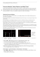
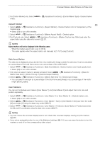
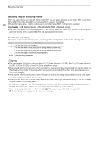
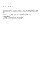
Onscreen Markers, Zebra Patterns and False Color 2 For [Center Marker] only: Select shape. > [A Assistance Functions] > [Center Marker Type] > Desired marker Aspect Marker 83 1 Select > [A Assistance Functions] > [Aspect Marker] > Desired marker color or transparency of the masked area. • Select [Off] to turn off the marker. 2 Select > [A Assistance Functions] > [Marker Aspect Ratio] > Desired option. 3 For [Custom] only: Select > [A Assistance Functions] > [Marker Custom Asp. Ratio] and enter the aspect ratio using the data entry screen (A 27). NOTES Aspect markers will not be displayed in the following cases. - When the marker aspect ratio is set to [16:9]. - The same applies when the aspect ratio is set manually to [1.78:1] using [Custom]. Safe Area Marker The safe area is displayed using a border line or by masking the image outside the safe area. It can be calculated as a percentage of the total frame area or as a percentage of the width/height. 1 Select > [A Assistance Functions] > [Safe Area Marker] > Desired marker color/mask opacity level. • Select [Off] to turn off the marker. 2 Only when an aspect marker is already activated: Select > [A Assistance Functions] > [Basis for Marker Safe Area] > [Whole Picture] or [Selected Aspect Marker]. 3 Select > [A Assistance Functions] > [Marker Safe Area %] > Desired percentage. • You can select the margin as a percentage of the total frame area [(Area)] or as a percentage of the width/ height [(Side Length)]. User Markers You can set 2 individual user markers ([User Marker 1] and [User Marker 2]) and adjust their color, size and position separately. 1 Select > [A Assistance Functions] > [User Marker 1] or [User Marker 2] > Desired marker color. • Select [Off] to turn off the marker. 2 Select > [A Assistance Functions] > [User Marker 1 Size] or [User Marker 2 Size] and enter the width [W] and height [H] using the data entry screen (A 27). 3 Select > [A Assistance Functions] > [User Marker 1 Position] or [User Marker 2 Position] and enter the [X] and [Y] coordinates using the data entry screen (A 27). NOTES • You can choose the onscreen display level to turn off all other onscreen displays, leaving only the markers (A 46). • If you set an assignable button to one of the [Markers:] settings (A 115), you can press the button to turn the markers on and off on the corresponding video output.
-
 1
1 -
2
-
3
-
4
-
5
-
6
-
7
-
8
-
9
-
10
-
11
-
12
-
13
-
14
-
15
-
16
-
17
-
18
-
19
-
20
-
21
-
22
-
23
-
24
-
25
-
26
-
27
-
28
-
29
-
30
-
31
-
32
-
33
-
34
-
35
-
36
-
37
-
38
-
39
-
40
-
41
-
42
-
43
-
44
-
45
-
46
-
47
-
48
-
49
-
50
-
51
-
52
-
53
-
54
-
55
-
56
-
57
-
58
-
59
-
60
-
61
-
62
-
63
-
64
-
65
-
66
-
67
-
68
-
69
-
70
-
71
-
72
-
73
-
74
-
75
-
76
-
77
-
 78
78 -
 79
79 -
 80
80 -
 81
81 -
 82
82 -
 83
83 -
 84
84 -
 85
85 -
 86
86 -
 87
87 -
 88
88 -
89
-
90
-
91
-
92
-
93
-
94
-
95
-
96
-
97
-
98
-
99
-
100
-
101
-
102
-
103
-
104
-
105
-
106
-
107
-
108
-
109
-
110
-
111
-
112
-
113
-
114
-
115
-
116
-
117
-
118
-
119
-
120
-
121
-
122
-
123
-
124
-
125
-
126
-
127
-
128
-
129
-
130
-
131
-
132
-
133
-
134
-
135
-
136
-
137
-
138
-
139
-
140
-
141
-
142
-
143
-
144
-
145
-
146
-
147
-
148
-
149
-
150
-
151
-
152
-
153
-
154
-
155
-
156
-
157
-
158
-
159
-
160
-
161
-
162
-
163
-
164
-
165
-
166
-
167
-
168
-
169
-
170
-
171
-
172
-
173
-
174
-
175
-
176
-
177
-
178
-
179
-
180
-
181
-
182
-
183
-
184
-
185
-
186
-
187
-
188
-
189
-
190
-
191
-
192
-
193
-
194
-
195
-
196
-
197
-
198
-
199
-
200
-
201
-
202
-
203
-
204
-
205
-
206
-
207
-
208
-
209
-
210
-
211
-
212
-
213
-
214
-
215
-
216
-
217
-
218
-
219
-
220
-
221
-
222
-
223
-
224
-
225
-
226
-
227
-
228
-
229
-
230
-
231
-
232
-
233
-
234
-
235
-
236
-
237
-
238
 |
 |