HP 6125G HP 6125G & 6125G/XG Blade Switches High Availability Configur - Page 100
Smart Link configuration task list, Configuring a Smart Link device, Configuration prerequisites
 |
View all HP 6125G manuals
Add to My Manuals
Save this manual to your list of manuals |
Page 100 highlights
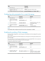
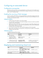
downlink ports to the up/down state of uplink ports, triggering Smart Link to perform link switchover on the downstream device. For more information about Monitor Link, see "Configuring Monitor Link." Smart Link configuration task list A smart link device is a device that supports Smart Link and is configured with a smart link group and a transmit control VLAN for flush message transmission. Device C and Device D in Figure 22 are two examples of smart link devices. An associated device is a device that supports Smart Link and receives flush messages sent from the specified control VLAN. Device A, Device B, and Device E in Figure 22 are examples of associated devices. Complete the following tasks to configure Smart Link: Task Configuring a Smart Link device Configuring an associated device Remarks Configuring protected VLANs for a smart link group Required Configuring member ports for a smart link group Required Configuring role preemption for a smart link group Optional Enabling the sending of flush messages Optional Enabling the receiving of flush messages Required Configuring a Smart Link device Configuration prerequisites • Before configuring a port as a smart link group member, shut down the port to prevent loops. You can bring up the port only after completing the smart link group configuration. • Disable the spanning tree feature and RRPP on the ports that you want to add to the smart link group, and make sure the ports are not member ports of any aggregation group or service loopback group. NOTE: A loop may occur on the network during the time when the spanning tree feature is disabled but Smart Link has not yet taken effect on a port. Configuring protected VLANs for a smart link group You can configure protected VLANs for a smart link group by referencing MSTIs. Before configuring the protected VLANs, configure the mappings between MSTIs and the VLANs to be protected. For more information about MSTI, see Layer 2-LAN Switching Configuration Guide. To configure the protected VLANs for a smart link group: 93
-
 1
1 -
2
-
3
-
4
-
5
-
6
-
7
-
8
-
9
-
10
-
11
-
12
-
13
-
14
-
15
-
16
-
17
-
18
-
19
-
20
-
21
-
22
-
23
-
24
-
25
-
26
-
27
-
28
-
29
-
30
-
31
-
32
-
33
-
34
-
35
-
36
-
37
-
38
-
39
-
40
-
41
-
42
-
43
-
44
-
45
-
46
-
47
-
48
-
49
-
50
-
51
-
52
-
53
-
54
-
55
-
56
-
57
-
58
-
59
-
60
-
61
-
62
-
63
-
64
-
65
-
66
-
67
-
68
-
69
-
70
-
71
-
72
-
73
-
74
-
75
-
76
-
77
-
78
-
79
-
80
-
81
-
82
-
83
-
84
-
85
-
86
-
87
-
88
-
89
-
90
-
91
-
92
-
93
-
94
-
 95
95 -
 96
96 -
 97
97 -
 98
98 -
 99
99 -
 100
100 -
 101
101 -
 102
102 -
 103
103 -
 104
104 -
 105
105 -
106
-
107
-
108
-
109
-
110
-
111
-
112
-
113
-
114
-
115
-
116
-
117
-
118
-
119
-
120
-
121
-
122
-
123
-
124
-
125
-
126
-
127
-
128
-
129
-
130
-
131
-
132
-
133
-
134
-
135
-
136
-
137
-
138
-
139
-
140
-
141
-
142
-
143
-
144
-
145
-
146
-
147
-
148
-
149
-
150
-
151
-
152
-
153
-
154
-
155
-
156
-
157
-
158
-
159
-
160
-
161
-
162
-
163
-
164
-
165
-
166
-
167
-
168
-
169
-
170
-
171
-
172
-
173
-
174
-
175
-
176
-
177
-
178
-
179
-
180
-
181
-
182
-
183
-
184
-
185
-
186
-
187
-
188
-
189
-
190
-
191
-
192
-
193
-
194
-
195
-
196
-
197
-
198
-
199
-
200
-
201
-
202
-
203
-
204
-
205
-
206
-
207
-
208
-
209
-
210
-
211
-
212
-
213
-
214
-
215
-
216
-
217
-
218
-
219
-
220
-
221
-
222
 |
 |