HP 6125G HP 6125G & 6125G/XG Blade Switches High Availability Configur - Page 31
CFD configuration example, Network requirements
 |
View all HP 6125G manuals
Add to My Manuals
Save this manual to your list of manuals |
Page 31 highlights
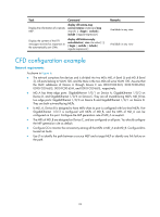
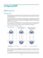
Task Command Display the information of a remote MEP. display cfd remote-mep service-instance instance-id mep mep-id [ | { begin | exclude | include } regular-expression ] Display the content of the LTR messages received as responses to the automatically sent LTMs. display cfd linktrace-reply auto-detection [ size size-value ] [ | { begin | exclude | include } regular-expression ] Remarks Available in any view Available in any view CFD configuration example Network requirements As shown in Figure 6: • The network comprises five devices and is divided into two MDs: MD_A (level 5) and MD_B (level 3). All ports belong to VLAN 100, and the MAs in the two MDs all serve VLAN 100. Assume that the MAC addresses of Device A through Device E are 0010-FC00-6511, 0010-FC00-6512, 0010-FC00-6513, 0010-FC00-6514, and 0010-FC00-6515, respectively. • MD_A has three edge ports: GigabitEthernet 1/0/1 on Device A, GigabitEthernet 1/0/3 on Device D, and GigabitEthernet 1/0/4 on Device E. They are all inward-facing MEPs. MD_B has two edge ports: GigabitEthernet 1/0/3 on Device B and GigabitEthernet 1/0/1 on Device D. They are both outward-facing MEPs. • In MD_A, Device B is designed to have MIPs when its port is configured with low-level MEPs. Port GigabitEthernet 1/0/3 is configured with MEPs of MD_B, and the MIPs of MD_A can be configured on this port. Configure the MIP generation rule of MD_A as explicit. • The MIPs of MD_B are designed on Device C, and are configured on all ports. You should configure the MIP generation rule as default. • Configure CC to monitor the connectivity among all the MEPs in MD_A and MD_B. Configure LB to locate link faults. • Use LT to identify the path between a source MEP and a target MEP or identify any link failure on the path. 24
-
 1
1 -
2
-
3
-
4
-
5
-
6
-
7
-
8
-
9
-
10
-
11
-
12
-
13
-
14
-
15
-
16
-
17
-
18
-
19
-
20
-
21
-
22
-
23
-
24
-
25
-
 26
26 -
 27
27 -
 28
28 -
 29
29 -
 30
30 -
 31
31 -
 32
32 -
 33
33 -
 34
34 -
 35
35 -
 36
36 -
37
-
38
-
39
-
40
-
41
-
42
-
43
-
44
-
45
-
46
-
47
-
48
-
49
-
50
-
51
-
52
-
53
-
54
-
55
-
56
-
57
-
58
-
59
-
60
-
61
-
62
-
63
-
64
-
65
-
66
-
67
-
68
-
69
-
70
-
71
-
72
-
73
-
74
-
75
-
76
-
77
-
78
-
79
-
80
-
81
-
82
-
83
-
84
-
85
-
86
-
87
-
88
-
89
-
90
-
91
-
92
-
93
-
94
-
95
-
96
-
97
-
98
-
99
-
100
-
101
-
102
-
103
-
104
-
105
-
106
-
107
-
108
-
109
-
110
-
111
-
112
-
113
-
114
-
115
-
116
-
117
-
118
-
119
-
120
-
121
-
122
-
123
-
124
-
125
-
126
-
127
-
128
-
129
-
130
-
131
-
132
-
133
-
134
-
135
-
136
-
137
-
138
-
139
-
140
-
141
-
142
-
143
-
144
-
145
-
146
-
147
-
148
-
149
-
150
-
151
-
152
-
153
-
154
-
155
-
156
-
157
-
158
-
159
-
160
-
161
-
162
-
163
-
164
-
165
-
166
-
167
-
168
-
169
-
170
-
171
-
172
-
173
-
174
-
175
-
176
-
177
-
178
-
179
-
180
-
181
-
182
-
183
-
184
-
185
-
186
-
187
-
188
-
189
-
190
-
191
-
192
-
193
-
194
-
195
-
196
-
197
-
198
-
199
-
200
-
201
-
202
-
203
-
204
-
205
-
206
-
207
-
208
-
209
-
210
-
211
-
212
-
213
-
214
-
215
-
216
-
217
-
218
-
219
-
220
-
221
-
222
 |
 |