HP 6125G HP 6125G & 6125G/XG Blade Switches High Availability Configur - Page 126
Assigning virtual MAC addresses,
 |
View all HP 6125G manuals
Add to My Manuals
Save this manual to your list of manuals |
Page 126 highlights
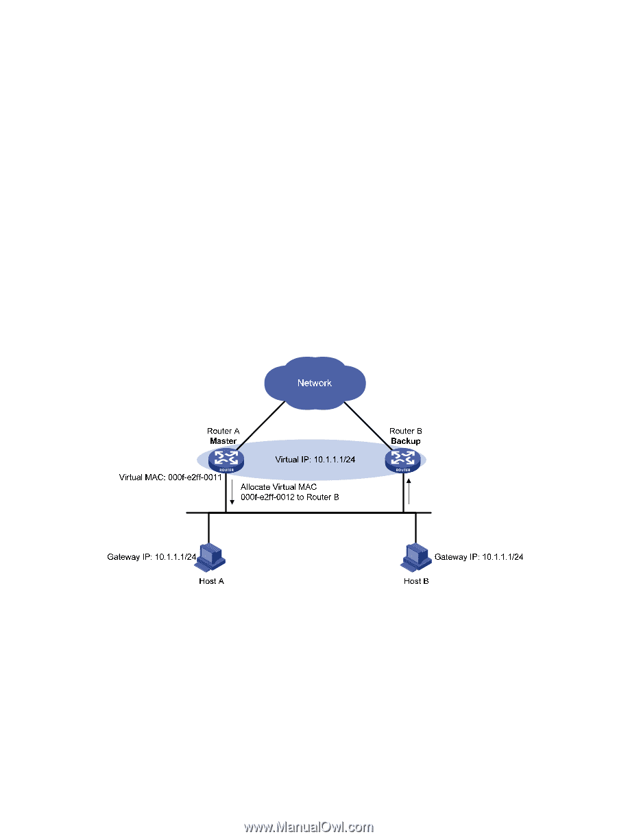
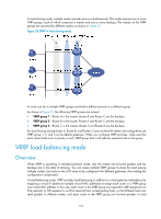
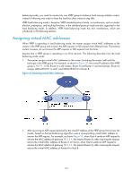
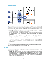
balancing mode, you need to create only one VRRP group to balance load among multiple routers, instead of allowing one router to bear the load but other routers to stay idle. VRRP load balancing mode is based on VRRP standard protocol mode, so mechanisms, such as master election, preemption, and tracking functions, in the standard protocol mode are also supported in the load balancing mode. In addition, VRRP load balancing mode has new mechanisms, which are introduced in the following sections. Assigning virtual MAC addresses When VRRP is operating in load balancing mode, the master assigns virtual MAC addresses to the routers in the VRRP group and answers the ARP requests or ND requests from different hosts. The backup routers, however, do not answer the ARP requests or ND requests from the hosts. Assume that a VRRP group is operating in an IPv4 network. The following describes how the load balancing mode works: 1. The master assigns virtual MAC addresses to the routers (including the master itself and the backups) in the VRRP group. For example, as shown in Figure 33, the virtual IP address of the VRRP group is 10.1.1.1/24; Router A is the master; Router B and Router C are the backups. Router A assigns 000f-e2ff-0011 to itself, and 000f-e2ff-0012 to Router B. Figure 33 Allocating virtual MAC addresses 2. After receiving an ARP request destined for the virtual IP address of the VRRP group from a host, the master, based on the load balancing algorithm, uses a corresponding virtual MAC address to answer the ARP request. For example, as shown Figure 34, when Host A sends an ARP request to retrieve the MAC address of gateway 10.1.1.1, the master (Router A), after receiving the request, returns the virtual MAC address of Router A to Host A; when Host B sends an ARP request to retrieve the MAC address of gateway 10.1.1.1, the master (Router A), after receiving the request, returns the virtual MAC address of Router B to Host B. 119
-
 1
1 -
2
-
3
-
4
-
5
-
6
-
7
-
8
-
9
-
10
-
11
-
12
-
13
-
14
-
15
-
16
-
17
-
18
-
19
-
20
-
21
-
22
-
23
-
24
-
25
-
26
-
27
-
28
-
29
-
30
-
31
-
32
-
33
-
34
-
35
-
36
-
37
-
38
-
39
-
40
-
41
-
42
-
43
-
44
-
45
-
46
-
47
-
48
-
49
-
50
-
51
-
52
-
53
-
54
-
55
-
56
-
57
-
58
-
59
-
60
-
61
-
62
-
63
-
64
-
65
-
66
-
67
-
68
-
69
-
70
-
71
-
72
-
73
-
74
-
75
-
76
-
77
-
78
-
79
-
80
-
81
-
82
-
83
-
84
-
85
-
86
-
87
-
88
-
89
-
90
-
91
-
92
-
93
-
94
-
95
-
96
-
97
-
98
-
99
-
100
-
101
-
102
-
103
-
104
-
105
-
106
-
107
-
108
-
109
-
110
-
111
-
112
-
113
-
114
-
115
-
116
-
117
-
118
-
119
-
120
-
 121
121 -
 122
122 -
 123
123 -
 124
124 -
 125
125 -
 126
126 -
 127
127 -
 128
128 -
 129
129 -
 130
130 -
 131
131 -
132
-
133
-
134
-
135
-
136
-
137
-
138
-
139
-
140
-
141
-
142
-
143
-
144
-
145
-
146
-
147
-
148
-
149
-
150
-
151
-
152
-
153
-
154
-
155
-
156
-
157
-
158
-
159
-
160
-
161
-
162
-
163
-
164
-
165
-
166
-
167
-
168
-
169
-
170
-
171
-
172
-
173
-
174
-
175
-
176
-
177
-
178
-
179
-
180
-
181
-
182
-
183
-
184
-
185
-
186
-
187
-
188
-
189
-
190
-
191
-
192
-
193
-
194
-
195
-
196
-
197
-
198
-
199
-
200
-
201
-
202
-
203
-
204
-
205
-
206
-
207
-
208
-
209
-
210
-
211
-
212
-
213
-
214
-
215
-
216
-
217
-
218
-
219
-
220
-
221
-
222
 |
 |