HP 6125G HP 6125G & 6125G/XG Blade Switches High Availability Configur - Page 215
Network diagram, Con to monitor track entry 1
 |
View all HP 6125G manuals
Add to My Manuals
Save this manual to your list of manuals |
Page 215 highlights
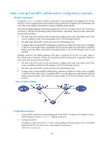
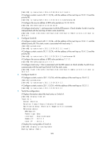
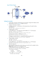
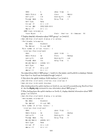
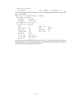
Figure 54 Network diagram Configuration procedure 1. Create VLANs, and assign corresponding ports to the VLANs. Configure the IP address of each VLAN interface as shown in Figure 54. (Details not shown.) 2. Configure a track entry on Switch A: # Configure track entry 1, and associate it with the physical status of the uplink interface VLAN-interface 3. [SwitchA] track 1 interface vlan-interface 3 3. Configure VRRP on Switch A: # Create VRRP group 1, and configure the virtual IP address 10.1.1.10 for the group. [SwitchA] interface vlan-interface 2 [SwitchA-Vlan-interface2] vrrp vrid 1 virtual-ip 10.1.1.10 # Set the priority of Switch A in VRRP group 1 to 110. [SwitchA-Vlan-interface2] vrrp vrid 1 priority 110 # Configure to monitor track entry 1, and specify the priority decrement as 30. [SwitchA-Vlan-interface2] vrrp vrid 1 track 1 reduced 30 4. Configure VRRP on Switch B: system-view [SwitchB] interface vlan-interface 2 # Create VRRP group 1, and configure the virtual IP address 10.1.1.10 for the group. [SwitchB-Vlan-interface2] vrrp vrid 1 virtual-ip 10.1.1.10 5. Verify the configuration: After configuration, ping Host B on Host A, and you can see that Host B is reachable. Use the display vrrp command to view the configuration result. # Display detailed information about VRRP group 1 on Switch A. [SwitchA-Vlan-interface2] display vrrp verbose IPv4 Standby Information: Run Mode : Standard Run Method : Virtual MAC Total number of virtual routers : 1 Interface Vlan-interface2 208
-
 1
1 -
2
-
3
-
4
-
5
-
6
-
7
-
8
-
9
-
10
-
11
-
12
-
13
-
14
-
15
-
16
-
17
-
18
-
19
-
20
-
21
-
22
-
23
-
24
-
25
-
26
-
27
-
28
-
29
-
30
-
31
-
32
-
33
-
34
-
35
-
36
-
37
-
38
-
39
-
40
-
41
-
42
-
43
-
44
-
45
-
46
-
47
-
48
-
49
-
50
-
51
-
52
-
53
-
54
-
55
-
56
-
57
-
58
-
59
-
60
-
61
-
62
-
63
-
64
-
65
-
66
-
67
-
68
-
69
-
70
-
71
-
72
-
73
-
74
-
75
-
76
-
77
-
78
-
79
-
80
-
81
-
82
-
83
-
84
-
85
-
86
-
87
-
88
-
89
-
90
-
91
-
92
-
93
-
94
-
95
-
96
-
97
-
98
-
99
-
100
-
101
-
102
-
103
-
104
-
105
-
106
-
107
-
108
-
109
-
110
-
111
-
112
-
113
-
114
-
115
-
116
-
117
-
118
-
119
-
120
-
121
-
122
-
123
-
124
-
125
-
126
-
127
-
128
-
129
-
130
-
131
-
132
-
133
-
134
-
135
-
136
-
137
-
138
-
139
-
140
-
141
-
142
-
143
-
144
-
145
-
146
-
147
-
148
-
149
-
150
-
151
-
152
-
153
-
154
-
155
-
156
-
157
-
158
-
159
-
160
-
161
-
162
-
163
-
164
-
165
-
166
-
167
-
168
-
169
-
170
-
171
-
172
-
173
-
174
-
175
-
176
-
177
-
178
-
179
-
180
-
181
-
182
-
183
-
184
-
185
-
186
-
187
-
188
-
189
-
190
-
191
-
192
-
193
-
194
-
195
-
196
-
197
-
198
-
199
-
200
-
201
-
202
-
203
-
204
-
205
-
206
-
207
-
208
-
209
-
 210
210 -
 211
211 -
 212
212 -
 213
213 -
 214
214 -
 215
215 -
 216
216 -
 217
217 -
 218
218 -
 219
219 -
 220
220 -
221
-
222
 |
 |
