HP 6125G HP 6125G & 6125G/XG Blade Switches High Availability Configur - Page 197
Network diagram, Con VRRP on Switch
 |
View all HP 6125G manuals
Add to My Manuals
Save this manual to your list of manuals |
Page 197 highlights
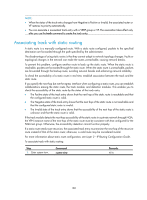
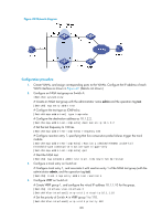
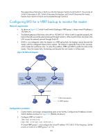
Figure 49 Network diagram Configuration procedure 1. Create VLANs, and assign corresponding ports to the VLANs. Configure the IP address of each VLAN interface as shown in Figure 49. (Details not shown.) 2. Configure an NQA test group on Switch A: system-view # Create an NQA test group with the administrator name admin and the operation tag test. [SwitchA] nqa entry admin test # Configure the test type as ICMP-echo. [SwitchA-nqa-admin-test] type icmp-echo # Configure the destination address as 10.1.2.2. [SwitchA-nqa-admin-test-icmp-echo] destination ip 10.1.2.2 # Set the test frequency to 100 ms. [SwitchA-nqa-admin-test-icmp-echo] frequency 100 # Configure reaction entry 1, specifying that five consecutive probe failures trigger the track module. [SwitchA-nqa-admin-test-icmp-echo] reaction 1 checked-element probe-fail threshold-type consecutive 5 action-type trigger-only [SwitchA-nqa-admin-test-icmp-echo] quit # Start the NQA test. [SwitchA] nqa schedule admin test start-time now lifetime forever 3. Configure a track entry on Switch A: # Configure track entry 1, and associate it with reaction entry 1 of the NQA test group (with the administrator admin, and the operation tag test). [SwitchA] track 1 nqa entry admin test reaction 1 4. Configure VRRP on Switch A: # Create VRRP group 1, and configure the virtual IP address 10.1.1.10 for the group. [SwitchA] interface vlan-interface 2 [SwitchA-Vlan-interface2] vrrp vrid 1 virtual-ip 10.1.1.10 # Set the priority of Switch A in VRRP group 1 to 110. [SwitchA-Vlan-interface2] vrrp vrid 1 priority 110 190
-
 1
1 -
2
-
3
-
4
-
5
-
6
-
7
-
8
-
9
-
10
-
11
-
12
-
13
-
14
-
15
-
16
-
17
-
18
-
19
-
20
-
21
-
22
-
23
-
24
-
25
-
26
-
27
-
28
-
29
-
30
-
31
-
32
-
33
-
34
-
35
-
36
-
37
-
38
-
39
-
40
-
41
-
42
-
43
-
44
-
45
-
46
-
47
-
48
-
49
-
50
-
51
-
52
-
53
-
54
-
55
-
56
-
57
-
58
-
59
-
60
-
61
-
62
-
63
-
64
-
65
-
66
-
67
-
68
-
69
-
70
-
71
-
72
-
73
-
74
-
75
-
76
-
77
-
78
-
79
-
80
-
81
-
82
-
83
-
84
-
85
-
86
-
87
-
88
-
89
-
90
-
91
-
92
-
93
-
94
-
95
-
96
-
97
-
98
-
99
-
100
-
101
-
102
-
103
-
104
-
105
-
106
-
107
-
108
-
109
-
110
-
111
-
112
-
113
-
114
-
115
-
116
-
117
-
118
-
119
-
120
-
121
-
122
-
123
-
124
-
125
-
126
-
127
-
128
-
129
-
130
-
131
-
132
-
133
-
134
-
135
-
136
-
137
-
138
-
139
-
140
-
141
-
142
-
143
-
144
-
145
-
146
-
147
-
148
-
149
-
150
-
151
-
152
-
153
-
154
-
155
-
156
-
157
-
158
-
159
-
160
-
161
-
162
-
163
-
164
-
165
-
166
-
167
-
168
-
169
-
170
-
171
-
172
-
173
-
174
-
175
-
176
-
177
-
178
-
179
-
180
-
181
-
182
-
183
-
184
-
185
-
186
-
187
-
188
-
189
-
190
-
191
-
 192
192 -
 193
193 -
 194
194 -
 195
195 -
 196
196 -
 197
197 -
 198
198 -
 199
199 -
 200
200 -
 201
201 -
 202
202 -
203
-
204
-
205
-
206
-
207
-
208
-
209
-
210
-
211
-
212
-
213
-
214
-
215
-
216
-
217
-
218
-
219
-
220
-
221
-
222
 |
 |
