HP 6125G HP 6125G & 6125G/XG Blade Switches High Availability Configur - Page 78
Configuration procedure, Device A through Device D form primary ring 1. Device A, Device B
 |
View all HP 6125G manuals
Add to My Manuals
Save this manual to your list of manuals |
Page 78 highlights
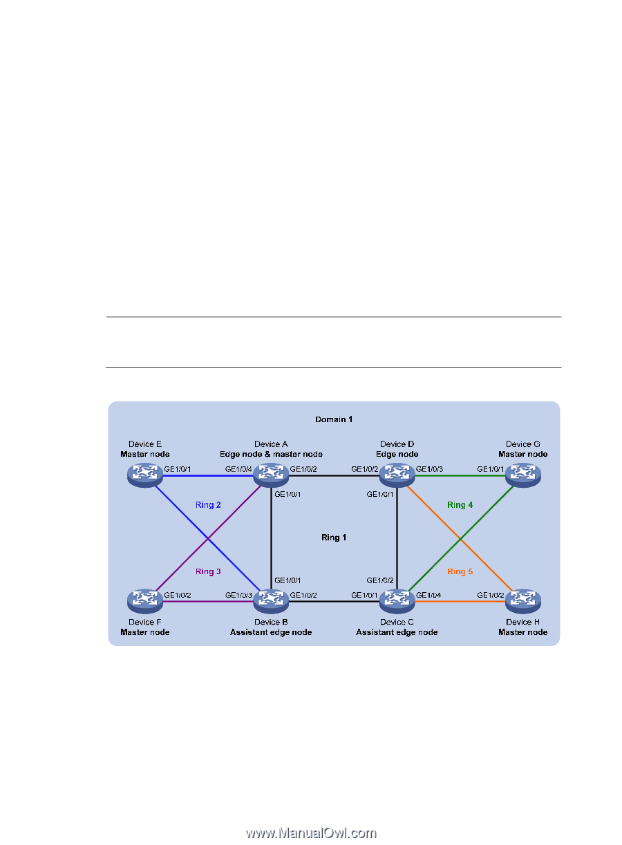
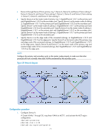
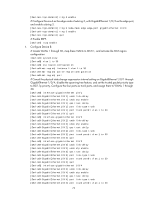
• Device A through Device D form primary ring 1. Device A, Device B, and Device E form subring 2. Device A, Device B, and Device F form subring 3. Device C, Device D, and Device G form subring 4. Device C, Device D, and Device H form subring 5. • Specify Device A as the master node of primary ring 1, GigabitEthernet 1/0/1 as the primary port and GigabitEthernet 1/0/2 as the secondary port. Specify Device E as the master node of subring 2, GigabitEthernet 1/0/1 as the primary port and GigabitEthernet 1/0/2 as the secondary port. Specify Device F as the master node of subring 3, GigabitEthernet 1/0/1 as the primary port and GigabitEthernet 1/0/2 as the secondary port. Specify Device G as the master node of subring 4, GigabitEthernet 1/0/1 as the primary port and GigabitEthernet 1/0/2 as the secondary port. Specify Device H as the master node of subring 5, GigabitEthernet 1/0/1 as the primary port and GigabitEthernet 1/0/2 as the secondary port. • Specify Device A as the edge node of the connected subrings, its GigabitEthernet 1/0/3 and GigabitEthernet 1/0/4 as the edge ports. Specify Device D as the transit node of the primary ring and edge node of the connected subrings, its GigabitEthernet 1/0/3 and GigabitEthernet 1/0/4 as the edge ports. Specify Device B and Device C as the transit node of the primary ring and assistant-edge nodes of the connected subrings, their GigabitEthernet 1/0/3 and GigabitEthernet 1/0/4 as the edge ports. NOTE: Configure the primary and secondary ports on the master nodes properly to make sure that other protocols still work normally when data VLANs are denied by the secondary ports. Figure 20 Network diagram GE1/0/2 GE1/0/1 GE1/0/3 GE1/0/4 GE1/0/4 GE1/0/3 GE1/0/2 GE1/0/1 Configuration procedure 1. Configure Device A: # Create VLANs 1 through 30, map these VLANs to MSTI 1, and activate the MST region configuration. system-view [DeviceA] vlan 1 to 30 [DeviceA] stp region-configuration 71
-
 1
1 -
2
-
3
-
4
-
5
-
6
-
7
-
8
-
9
-
10
-
11
-
12
-
13
-
14
-
15
-
16
-
17
-
18
-
19
-
20
-
21
-
22
-
23
-
24
-
25
-
26
-
27
-
28
-
29
-
30
-
31
-
32
-
33
-
34
-
35
-
36
-
37
-
38
-
39
-
40
-
41
-
42
-
43
-
44
-
45
-
46
-
47
-
48
-
49
-
50
-
51
-
52
-
53
-
54
-
55
-
56
-
57
-
58
-
59
-
60
-
61
-
62
-
63
-
64
-
65
-
66
-
67
-
68
-
69
-
70
-
71
-
72
-
 73
73 -
 74
74 -
 75
75 -
 76
76 -
 77
77 -
 78
78 -
 79
79 -
 80
80 -
 81
81 -
 82
82 -
 83
83 -
84
-
85
-
86
-
87
-
88
-
89
-
90
-
91
-
92
-
93
-
94
-
95
-
96
-
97
-
98
-
99
-
100
-
101
-
102
-
103
-
104
-
105
-
106
-
107
-
108
-
109
-
110
-
111
-
112
-
113
-
114
-
115
-
116
-
117
-
118
-
119
-
120
-
121
-
122
-
123
-
124
-
125
-
126
-
127
-
128
-
129
-
130
-
131
-
132
-
133
-
134
-
135
-
136
-
137
-
138
-
139
-
140
-
141
-
142
-
143
-
144
-
145
-
146
-
147
-
148
-
149
-
150
-
151
-
152
-
153
-
154
-
155
-
156
-
157
-
158
-
159
-
160
-
161
-
162
-
163
-
164
-
165
-
166
-
167
-
168
-
169
-
170
-
171
-
172
-
173
-
174
-
175
-
176
-
177
-
178
-
179
-
180
-
181
-
182
-
183
-
184
-
185
-
186
-
187
-
188
-
189
-
190
-
191
-
192
-
193
-
194
-
195
-
196
-
197
-
198
-
199
-
200
-
201
-
202
-
203
-
204
-
205
-
206
-
207
-
208
-
209
-
210
-
211
-
212
-
213
-
214
-
215
-
216
-
217
-
218
-
219
-
220
-
221
-
222
 |
 |