HP 6125G HP 6125G & 6125G/XG Blade Switches High Availability Configur - Page 99
How Smart Link works, Link backup mechanism, Topology change mechanism, Role preemption mechanism
 |
View all HP 6125G manuals
Add to My Manuals
Save this manual to your list of manuals |
Page 99 highlights
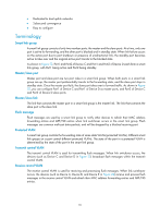
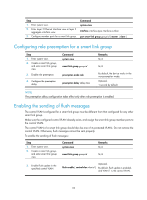
How Smart Link works Link backup mechanism As shown in Figure 22, the link on Port1 of Device C is the master link, and the link on Port2 of Device C is the slave link. Typically, Port1 is in forwarding state, and Port2 is in standby state. When the master link fails, Port2 takes over to forward traffic and Port1 is blocked and placed in standby state. NOTE: When a port switches to the forwarding state, the system outputs log information to notify the user of the port state change. Topology change mechanism Because link switchover can outdate the MAC address forwarding entries and ARP/ND entries on all devices, you need a forwarding entry update mechanism to ensure proper transmission. By far, the following two update mechanisms are provided: • Uplink traffic-triggered MAC address learning, where update is triggered by uplink traffic. This mechanism is applicable to environments with devices not supporting Smart Link, including devices of other vendors'. • Flush update where a Smart Link-enabled device updates its information by transmitting flush messages over the backup link to its upstream devices. This mechanism requires the upstream devices to be capable of recognizing Smart Link flush messages to update its MAC address forwarding entries and ARP/ND entries. Role preemption mechanism As shown in Figure 22, the link on Port1 of Device C is the master link, and the link on Port2 of Device C is the slave link. Once the master link fails, Port1 is automatically blocked and placed in standby state, and Port2 takes over to forward traffic. When the master link recovers, one of the following occurs: • If the smart link group is not configured with role preemption, to keep traffic forwarding stable, Port1 that has been blocked due to link failure does not immediately take over to forward traffic. Rather, it stays blocked until the next link switchover. • If the smart link group is configured with role preemption, Port1 takes over to forward traffic as soon as its link recovers, and Port2 is automatically blocked and placed in standby state. Load sharing mechanism A ring network may carry traffic of multiple VLANs. Smart Link can forward traffic of different VLANs in different smart link groups, implementing load sharing. To implement load sharing, you can assign a port to multiple smart link groups (each configured with different protected VLANs), making sure that the state of the port is different in these smart link groups. In this way, traffic of different VLANs can be forwarded along different paths. You can configure protected VLANs for a smart link group by referencing Multiple Spanning Tree Instances (MSTIs). Smart Link collaboration mechanisms Smart Link cannot sense by itself when faults occur on the uplink of the upstream devices, or when faults are cleared. To monitor the uplink status of the upstream devices, you can configure the Monitor Link function to monitor the uplink ports of the upstream devices. Monitor Link adapts the up/down state of 92
-
 1
1 -
2
-
3
-
4
-
5
-
6
-
7
-
8
-
9
-
10
-
11
-
12
-
13
-
14
-
15
-
16
-
17
-
18
-
19
-
20
-
21
-
22
-
23
-
24
-
25
-
26
-
27
-
28
-
29
-
30
-
31
-
32
-
33
-
34
-
35
-
36
-
37
-
38
-
39
-
40
-
41
-
42
-
43
-
44
-
45
-
46
-
47
-
48
-
49
-
50
-
51
-
52
-
53
-
54
-
55
-
56
-
57
-
58
-
59
-
60
-
61
-
62
-
63
-
64
-
65
-
66
-
67
-
68
-
69
-
70
-
71
-
72
-
73
-
74
-
75
-
76
-
77
-
78
-
79
-
80
-
81
-
82
-
83
-
84
-
85
-
86
-
87
-
88
-
89
-
90
-
91
-
92
-
93
-
 94
94 -
 95
95 -
 96
96 -
 97
97 -
 98
98 -
 99
99 -
 100
100 -
 101
101 -
 102
102 -
 103
103 -
 104
104 -
105
-
106
-
107
-
108
-
109
-
110
-
111
-
112
-
113
-
114
-
115
-
116
-
117
-
118
-
119
-
120
-
121
-
122
-
123
-
124
-
125
-
126
-
127
-
128
-
129
-
130
-
131
-
132
-
133
-
134
-
135
-
136
-
137
-
138
-
139
-
140
-
141
-
142
-
143
-
144
-
145
-
146
-
147
-
148
-
149
-
150
-
151
-
152
-
153
-
154
-
155
-
156
-
157
-
158
-
159
-
160
-
161
-
162
-
163
-
164
-
165
-
166
-
167
-
168
-
169
-
170
-
171
-
172
-
173
-
174
-
175
-
176
-
177
-
178
-
179
-
180
-
181
-
182
-
183
-
184
-
185
-
186
-
187
-
188
-
189
-
190
-
191
-
192
-
193
-
194
-
195
-
196
-
197
-
198
-
199
-
200
-
201
-
202
-
203
-
204
-
205
-
206
-
207
-
208
-
209
-
210
-
211
-
212
-
213
-
214
-
215
-
216
-
217
-
218
-
219
-
220
-
221
-
222
 |
 |