HP 6125G HP 6125G & 6125G/XG Blade Switches High Availability Configur - Page 102
Configuring role preemption for a smart link group, Enabling the sending of flush messages, Command
 |
View all HP 6125G manuals
Add to My Manuals
Save this manual to your list of manuals |
Page 102 highlights
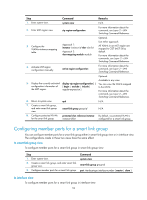
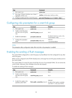
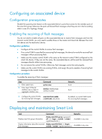
Step 1. Enter system view. 2. Enter Layer 2 Ethernet interface view or layer 2 aggregate interface view. 3. Configure member ports for a smart link group. Command system-view interface interface-type interface-number port smart-link group group-id { master | slave } Configuring role preemption for a smart link group Step 1. Enter system view. 2. Create a smart link group, and enter smart link group view. 3. Enable role preemption. 4. Configure the preemption delay. Command system-view smart-link group group-id preemption mode role preemption delay delay-time Remarks N/A N/A By default, the device works in the non-preemption mode. Optional. 1 second by default. NOTE: The preemption delay configuration takes effect only after role preemption is enabled. Enabling the sending of flush messages The control VLAN configured for a smart link group must be different from that configured for any other smart link group. Make sure the configured control VLAN already exists, and assign the smart link group member ports to the control VLAN. The control VLAN of a smart link group should also be one of its protected VLANs. Do not remove the control VLAN. Otherwise, flush messages cannot be sent properly. To enable the sending of flush messages: Step 1. Enter system view. 2. Create a smart link group, and enter smart link group view. Command system-view smart-link group group-id Remarks N/A N/A 3. Enable flush update in the specified control VLAN. flush enable [ control-vlan vlan-id ] Optional. By default, flush update is enabled, and VLAN 1 is the control VLAN. 95
-
 1
1 -
2
-
3
-
4
-
5
-
6
-
7
-
8
-
9
-
10
-
11
-
12
-
13
-
14
-
15
-
16
-
17
-
18
-
19
-
20
-
21
-
22
-
23
-
24
-
25
-
26
-
27
-
28
-
29
-
30
-
31
-
32
-
33
-
34
-
35
-
36
-
37
-
38
-
39
-
40
-
41
-
42
-
43
-
44
-
45
-
46
-
47
-
48
-
49
-
50
-
51
-
52
-
53
-
54
-
55
-
56
-
57
-
58
-
59
-
60
-
61
-
62
-
63
-
64
-
65
-
66
-
67
-
68
-
69
-
70
-
71
-
72
-
73
-
74
-
75
-
76
-
77
-
78
-
79
-
80
-
81
-
82
-
83
-
84
-
85
-
86
-
87
-
88
-
89
-
90
-
91
-
92
-
93
-
94
-
95
-
96
-
 97
97 -
 98
98 -
 99
99 -
 100
100 -
 101
101 -
 102
102 -
 103
103 -
 104
104 -
 105
105 -
 106
106 -
 107
107 -
108
-
109
-
110
-
111
-
112
-
113
-
114
-
115
-
116
-
117
-
118
-
119
-
120
-
121
-
122
-
123
-
124
-
125
-
126
-
127
-
128
-
129
-
130
-
131
-
132
-
133
-
134
-
135
-
136
-
137
-
138
-
139
-
140
-
141
-
142
-
143
-
144
-
145
-
146
-
147
-
148
-
149
-
150
-
151
-
152
-
153
-
154
-
155
-
156
-
157
-
158
-
159
-
160
-
161
-
162
-
163
-
164
-
165
-
166
-
167
-
168
-
169
-
170
-
171
-
172
-
173
-
174
-
175
-
176
-
177
-
178
-
179
-
180
-
181
-
182
-
183
-
184
-
185
-
186
-
187
-
188
-
189
-
190
-
191
-
192
-
193
-
194
-
195
-
196
-
197
-
198
-
199
-
200
-
201
-
202
-
203
-
204
-
205
-
206
-
207
-
208
-
209
-
210
-
211
-
212
-
213
-
214
-
215
-
216
-
217
-
218
-
219
-
220
-
221
-
222
 |
 |