HP 6125G HP 6125G & 6125G/XG Blade Switches High Availability Configur - Page 165
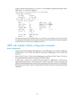
from Host A to Host B are forwarded by Switch B
 |
View all HP 6125G manuals
Add to My Manuals
Save this manual to your list of manuals |
Page 165 highlights
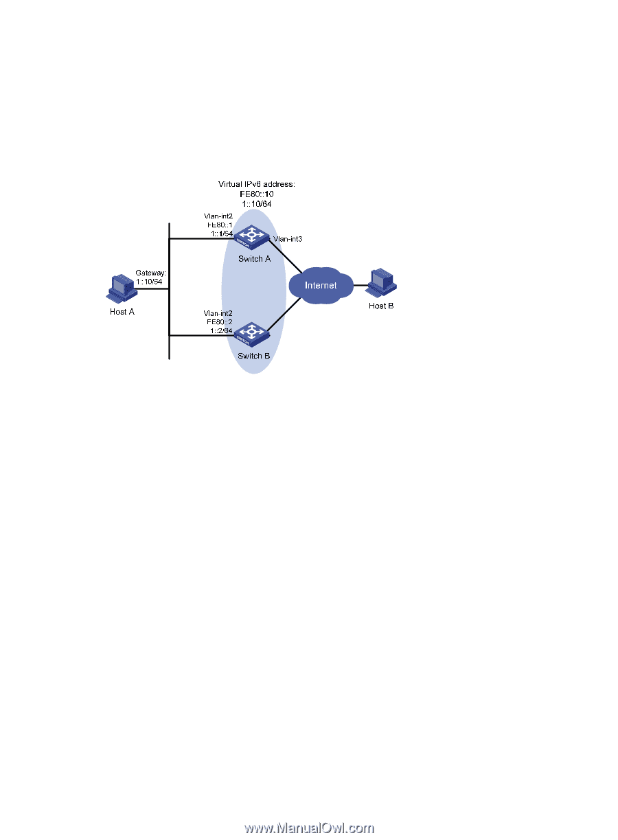
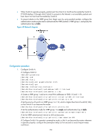
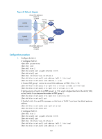
• When Switch A operates properly, packets sent from Host A to Host B are forwarded by Switch A. If VLAN-interface 3 through which Switch A connects to the Internet is not available, packets sent from Host A to Host B are forwarded by Switch B. • To prevent attacks to the VRRP group from illegal users by using spoofed packets, configure the authentication mode as plain text to authenticate the VRRP packets in VRRP group 1, and specify the authentication key as hello. Figure 42 Network diagram Configuration procedure 1. Configure Switch A: # Configure VLAN 2. system-view [SwitchA] ipv6 [SwitchA] vlan 2 [SwitchA-vlan2] port gigabitethernet 1/0/5 [SwitchA-vlan2] quit [SwitchA] interface vlan-interface 2 [SwitchA-Vlan-interface2] ipv6 address fe80::1 link-local [SwitchA-Vlan-interface2] ipv6 address 1::1 64 # Create a VRRP group 1 and set its virtual IPv6 addresses to FE80::10 and 1::10. [SwitchA-Vlan-interface2] vrrp ipv6 vrid 1 virtual-ip fe80::10 link-local [SwitchA-Vlan-interface2] vrrp ipv6 vrid 1 virtual-ip 1::10 # Set the priority of Switch A in VRRP group 1 to 110, which is higher than that of Switch B (100), so that Switch A can become the master. [SwitchA-Vlan-interface2] vrrp ipv6 vrid 1 priority 110 # Set the authentication mode for VRRP group 1 to simple and authentication key to hello. [SwitchA-Vlan-interface2] vrrp ipv6 vrid 1 authentication-mode simple hello # Set the VRRP advertisement interval to 400 centiseconds. [SwitchA-Vlan-interface2] vrrp ipv6 vrid 1 timer advertise 400 # Configure Switch A to operate in preemptive mode, so that it can become the master whenever it operates properly; configure the preemption delay as five seconds to avoid frequent status switchover. 158
-
 1
1 -
2
-
3
-
4
-
5
-
6
-
7
-
8
-
9
-
10
-
11
-
12
-
13
-
14
-
15
-
16
-
17
-
18
-
19
-
20
-
21
-
22
-
23
-
24
-
25
-
26
-
27
-
28
-
29
-
30
-
31
-
32
-
33
-
34
-
35
-
36
-
37
-
38
-
39
-
40
-
41
-
42
-
43
-
44
-
45
-
46
-
47
-
48
-
49
-
50
-
51
-
52
-
53
-
54
-
55
-
56
-
57
-
58
-
59
-
60
-
61
-
62
-
63
-
64
-
65
-
66
-
67
-
68
-
69
-
70
-
71
-
72
-
73
-
74
-
75
-
76
-
77
-
78
-
79
-
80
-
81
-
82
-
83
-
84
-
85
-
86
-
87
-
88
-
89
-
90
-
91
-
92
-
93
-
94
-
95
-
96
-
97
-
98
-
99
-
100
-
101
-
102
-
103
-
104
-
105
-
106
-
107
-
108
-
109
-
110
-
111
-
112
-
113
-
114
-
115
-
116
-
117
-
118
-
119
-
120
-
121
-
122
-
123
-
124
-
125
-
126
-
127
-
128
-
129
-
130
-
131
-
132
-
133
-
134
-
135
-
136
-
137
-
138
-
139
-
140
-
141
-
142
-
143
-
144
-
145
-
146
-
147
-
148
-
149
-
150
-
151
-
152
-
153
-
154
-
155
-
156
-
157
-
158
-
159
-
 160
160 -
 161
161 -
 162
162 -
 163
163 -
 164
164 -
 165
165 -
 166
166 -
 167
167 -
 168
168 -
 169
169 -
 170
170 -
171
-
172
-
173
-
174
-
175
-
176
-
177
-
178
-
179
-
180
-
181
-
182
-
183
-
184
-
185
-
186
-
187
-
188
-
189
-
190
-
191
-
192
-
193
-
194
-
195
-
196
-
197
-
198
-
199
-
200
-
201
-
202
-
203
-
204
-
205
-
206
-
207
-
208
-
209
-
210
-
211
-
212
-
213
-
214
-
215
-
216
-
217
-
218
-
219
-
220
-
221
-
222
 |
 |