HP 6125G HP 6125G & 6125G/XG Blade Switches High Availability Configur - Page 211
Static routing-Track-BFD collaboration configuration example, Network requirements, Configuration
 |
View all HP 6125G manuals
Add to My Manuals
Save this manual to your list of manuals |
Page 211 highlights
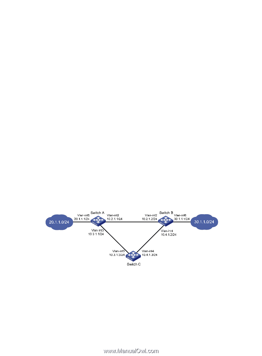
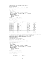
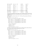
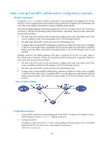
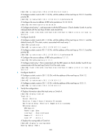
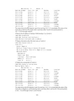
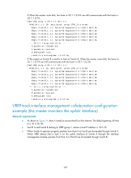
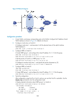
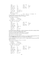
Static routing-Track-BFD collaboration configuration example Network requirements As shown in Figure 53, Switch A, Switch B, and Switch C are connected to two segments 20.1.1.0/24 and 30.1.1.0/24. Configure static routes on these routers so that the two segments can communicate with each other, and configure route backup to improve reliability of the network. Switch A is the default gateway of the hosts in segment 20.1.1.0/24. Two static routes to 30.1.1.0/24 exist on Switch A, with the next hop being Switch B and Switch C, respectively. These two static routes back up each other as follows: • The static route with Switch B as the next hop has a higher priority and is the master route. If this route is available, Switch A forwards packets to 30.1.1.0/24 through Switch B. • The static route with Switch C as the next hop acts as the backup route. • Configure static routing-track-BFD collaboration to determine whether the master route is available in real time. If the master route is unavailable, BFD can quickly detect the route failure to make the backup route take effect, and Switch A forwards packets to 30.1.1.0/24 through Switch C and Switch B. Similarly, Switch B is the default gateway of the hosts in segment 30.1.1.0/24. Two static routes to 20.1.1.0/24 exist on Switch B, with the next hop being Switch A and Switch C, respectively. These two static routes back up each other as follows: • The static route with Switch A as the next hop has a higher priority and is the master route. If this route is available, Switch B forwards packets to 20.1.1.0/24 through Switch A. • The static route with Switch C as the next hop acts as the backup route. • Configure static routing-track-BFD collaboration to determine whether the master route is available in real time. If the master route is unavailable, BFD can quickly detect the route failure to make the backup route take effect, and Switch B forwards packets to 20.1.1.0/24 through Switch C and Switch A. Figure 53 Network diagram Configuration procedure 1. Create VLANs, and assign corresponding ports to the VLANs. Configure the IP address of each VLAN interface as shown in Figure 53. (Details not shown.) 2. Configure Switch A: # Configure a static route to 30.1.1.0/24, with the address of the next hop as 10.2.1.2 and the default priority 60. This static route is associated with track entry 1. system-view 204
-
 1
1 -
2
-
3
-
4
-
5
-
6
-
7
-
8
-
9
-
10
-
11
-
12
-
13
-
14
-
15
-
16
-
17
-
18
-
19
-
20
-
21
-
22
-
23
-
24
-
25
-
26
-
27
-
28
-
29
-
30
-
31
-
32
-
33
-
34
-
35
-
36
-
37
-
38
-
39
-
40
-
41
-
42
-
43
-
44
-
45
-
46
-
47
-
48
-
49
-
50
-
51
-
52
-
53
-
54
-
55
-
56
-
57
-
58
-
59
-
60
-
61
-
62
-
63
-
64
-
65
-
66
-
67
-
68
-
69
-
70
-
71
-
72
-
73
-
74
-
75
-
76
-
77
-
78
-
79
-
80
-
81
-
82
-
83
-
84
-
85
-
86
-
87
-
88
-
89
-
90
-
91
-
92
-
93
-
94
-
95
-
96
-
97
-
98
-
99
-
100
-
101
-
102
-
103
-
104
-
105
-
106
-
107
-
108
-
109
-
110
-
111
-
112
-
113
-
114
-
115
-
116
-
117
-
118
-
119
-
120
-
121
-
122
-
123
-
124
-
125
-
126
-
127
-
128
-
129
-
130
-
131
-
132
-
133
-
134
-
135
-
136
-
137
-
138
-
139
-
140
-
141
-
142
-
143
-
144
-
145
-
146
-
147
-
148
-
149
-
150
-
151
-
152
-
153
-
154
-
155
-
156
-
157
-
158
-
159
-
160
-
161
-
162
-
163
-
164
-
165
-
166
-
167
-
168
-
169
-
170
-
171
-
172
-
173
-
174
-
175
-
176
-
177
-
178
-
179
-
180
-
181
-
182
-
183
-
184
-
185
-
186
-
187
-
188
-
189
-
190
-
191
-
192
-
193
-
194
-
195
-
196
-
197
-
198
-
199
-
200
-
201
-
202
-
203
-
204
-
205
-
 206
206 -
 207
207 -
 208
208 -
 209
209 -
 210
210 -
 211
211 -
 212
212 -
 213
213 -
 214
214 -
 215
215 -
 216
216 -
217
-
218
-
219
-
220
-
221
-
222
 |
 |