HP 6125G HP 6125G & 6125G/XG Blade Switches High Availability Configur - Page 108
Multiple smart link groups load sharing configuration example, Network requirements
 |
View all HP 6125G manuals
Add to My Manuals
Save this manual to your list of manuals |
Page 108 highlights
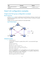
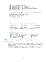
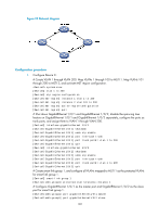
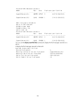
[DeviceA] interface gigabitethernet 1/0/2 [DeviceA-GigabitEthernet1/0/2] port link-type trunk [DeviceA-GigabitEthernet1/0/2] port trunk permit vlan 1 to 30 [DeviceA-GigabitEthernet1/0/2] smart-link flush enable control-vlan 10 20 [DeviceA-GigabitEthernet1/0/2] quit 6. Verify the configuration: You can use the display smart-link group command to display the smart link group configuration on a device. # Display the smart link group configuration on Device C. [DeviceC] display smart-link group 1 Smart link group 1 information: Device ID: 000f-e23d-5af0 Preemption mode: NONE Preemption delay: 1(s) Control VLAN: 10 Protected VLAN: Reference Instance 1 Member Role State Flush-count Last-flush-time GigabitEthernet1/0/1 MASTER ACTVIE 5 16:37:20 2010/02/21 GigabitEthernet1/0/2 SLAVE STANDBY 1 17:45:20 2010/02/21 You can use the display smart-link flush command to display the flush messages received on a device. # Display the flush messages received on Device B. [DeviceB] display smart-link flush Received flush packets : 5 Receiving interface of the last flush packet : GigabitEthernet1/0/3 Receiving time of the last flush packet : 16:25:21 2009/02/21 Device ID of the last flush packet : 000f-e23d-5af0 Control VLAN of the last flush packet : 10 Multiple smart link groups load sharing configuration example Network requirements As shown in Figure 24, Device C is a smart link device, and Device A, Device B, and Device D are associated devices. Traffic of VLANs 1 through 200 on Device C are dually uplinked to Device A by Device B and Device D. Implement dual uplink backup and load sharing on Device C: traffic of VLANs 1 through 100 is uplinked to Device A by Device B; traffic of VLANs 101 through 200 is uplinked to Device A by Device D. 101
-
 1
1 -
2
-
3
-
4
-
5
-
6
-
7
-
8
-
9
-
10
-
11
-
12
-
13
-
14
-
15
-
16
-
17
-
18
-
19
-
20
-
21
-
22
-
23
-
24
-
25
-
26
-
27
-
28
-
29
-
30
-
31
-
32
-
33
-
34
-
35
-
36
-
37
-
38
-
39
-
40
-
41
-
42
-
43
-
44
-
45
-
46
-
47
-
48
-
49
-
50
-
51
-
52
-
53
-
54
-
55
-
56
-
57
-
58
-
59
-
60
-
61
-
62
-
63
-
64
-
65
-
66
-
67
-
68
-
69
-
70
-
71
-
72
-
73
-
74
-
75
-
76
-
77
-
78
-
79
-
80
-
81
-
82
-
83
-
84
-
85
-
86
-
87
-
88
-
89
-
90
-
91
-
92
-
93
-
94
-
95
-
96
-
97
-
98
-
99
-
100
-
101
-
102
-
 103
103 -
 104
104 -
 105
105 -
 106
106 -
 107
107 -
 108
108 -
 109
109 -
 110
110 -
 111
111 -
 112
112 -
 113
113 -
114
-
115
-
116
-
117
-
118
-
119
-
120
-
121
-
122
-
123
-
124
-
125
-
126
-
127
-
128
-
129
-
130
-
131
-
132
-
133
-
134
-
135
-
136
-
137
-
138
-
139
-
140
-
141
-
142
-
143
-
144
-
145
-
146
-
147
-
148
-
149
-
150
-
151
-
152
-
153
-
154
-
155
-
156
-
157
-
158
-
159
-
160
-
161
-
162
-
163
-
164
-
165
-
166
-
167
-
168
-
169
-
170
-
171
-
172
-
173
-
174
-
175
-
176
-
177
-
178
-
179
-
180
-
181
-
182
-
183
-
184
-
185
-
186
-
187
-
188
-
189
-
190
-
191
-
192
-
193
-
194
-
195
-
196
-
197
-
198
-
199
-
200
-
201
-
202
-
203
-
204
-
205
-
206
-
207
-
208
-
209
-
210
-
211
-
212
-
213
-
214
-
215
-
216
-
217
-
218
-
219
-
220
-
221
-
222
 |
 |