HP 6125G HP 6125G & 6125G/XG Blade Switches High Availability Configur - Page 55
RRPP ring, Control VLAN and data VLAN, Node, Health state, Disconnect state, Master node, Transit
 |
View all HP 6125G manuals
Add to My Manuals
Save this manual to your list of manuals |
Page 55 highlights
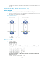
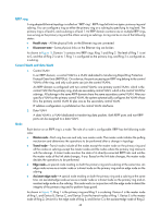
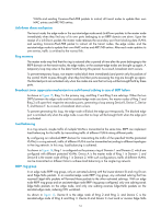
RRPP ring A ring-shaped Ethernet topology is called an "RRPP ring". RRPP rings fall into two types: primary ring and subring. You can configure a ring as either the primary ring or a subring by specifying its ring level. The primary ring is of level 0, and a subring is of level 1. An RRPP domain contains one or multiple RRPP rings, one serving as the primary ring and the others serving as subrings. A ring can be in one of the following states: • Health state-All the physical links on the Ethernet ring are connected • Disconnect state-Some physical links on the Ethernet ring are broken As shown in Figure 11, Domain 1 contains two RRPP rings: Ring 1 and Ring 2. The level of Ring 1 is set to 0, and that of Ring 2 is set to 1. Ring 1 is configured as the primary ring, and Ring 2 is configured as a subring. Control VLAN and data VLAN 1. Control VLAN In an RRPP domain, a control VLAN is a VLAN dedicated to transferring Rapid Ring Protection Protocol Data Units (RRPPDUs). On a device, the ports accessing an RRPP ring belong to the control VLANs of the ring, and only such ports can join the control VLANs. An RRPP domain is configured with two control VLANs: one primary control VLAN, which is the control VLAN for the primary ring, and one secondary control VLAN, which is the control VLAN for subrings. All subrings in the same RRPP domain share the same secondary control VLAN. After you specify a VLAN as the primary control VLAN, the system automatically configures the VLAN whose ID is the primary control VLAN ID plus one as the secondary control VLAN. IP address configuration is prohibited on the control VLAN interfaces. 2. Data VLAN A data VLAN is a VLAN dedicated to transferring data packets. Both RRPP ports and non-RRPP ports can be assigned to a data VLAN. Node Each device on an RRPP ring is a node. The role of a node is configurable. RRPP has the following node roles: • Master node-Each ring has one and only one master node. The master node initiates the polling mechanism and determines the operations to be performed after a change in topology. • Transit node-Transit nodes include all the nodes except the master node on the primary ring and all the nodes on subrings except the master nodes and the nodes where the primary ring intersects with the subrings. A transit node monitors the state of its directly-connected RRPP links and notifies the master node of the link state changes, if any. Based on the link state changes, the master node decides the operations to be performed. • Edge node-A special node residing on both the primary ring and a subring at the same time. An edge node serves as a master node or a transit node on the primary ring and an edge node on the subring. • Assistant-edge node-A special node residing on both the primary ring and a subring at the same time. An assistant-edge node serves as a master node or a transit node on the primary ring and an assistant-edge node on the subring. This node works in conjunction with the edge node to detect the integrity of the primary ring and to perform loop guard. As shown in Figure 11, Ring 1 is the primary ring and Ring 2 is a subring. Device A is the master node of Ring 1, and Device B, Device C, and Device D are the transit nodes of Ring 1. Device E is the master node of Ring 2, Device B is the edge node of Ring 2, and Device C is the assistant-edge node of Ring 2. 48
-
 1
1 -
2
-
3
-
4
-
5
-
6
-
7
-
8
-
9
-
10
-
11
-
12
-
13
-
14
-
15
-
16
-
17
-
18
-
19
-
20
-
21
-
22
-
23
-
24
-
25
-
26
-
27
-
28
-
29
-
30
-
31
-
32
-
33
-
34
-
35
-
36
-
37
-
38
-
39
-
40
-
41
-
42
-
43
-
44
-
45
-
46
-
47
-
48
-
49
-
 50
50 -
 51
51 -
 52
52 -
 53
53 -
 54
54 -
 55
55 -
 56
56 -
 57
57 -
 58
58 -
 59
59 -
 60
60 -
61
-
62
-
63
-
64
-
65
-
66
-
67
-
68
-
69
-
70
-
71
-
72
-
73
-
74
-
75
-
76
-
77
-
78
-
79
-
80
-
81
-
82
-
83
-
84
-
85
-
86
-
87
-
88
-
89
-
90
-
91
-
92
-
93
-
94
-
95
-
96
-
97
-
98
-
99
-
100
-
101
-
102
-
103
-
104
-
105
-
106
-
107
-
108
-
109
-
110
-
111
-
112
-
113
-
114
-
115
-
116
-
117
-
118
-
119
-
120
-
121
-
122
-
123
-
124
-
125
-
126
-
127
-
128
-
129
-
130
-
131
-
132
-
133
-
134
-
135
-
136
-
137
-
138
-
139
-
140
-
141
-
142
-
143
-
144
-
145
-
146
-
147
-
148
-
149
-
150
-
151
-
152
-
153
-
154
-
155
-
156
-
157
-
158
-
159
-
160
-
161
-
162
-
163
-
164
-
165
-
166
-
167
-
168
-
169
-
170
-
171
-
172
-
173
-
174
-
175
-
176
-
177
-
178
-
179
-
180
-
181
-
182
-
183
-
184
-
185
-
186
-
187
-
188
-
189
-
190
-
191
-
192
-
193
-
194
-
195
-
196
-
197
-
198
-
199
-
200
-
201
-
202
-
203
-
204
-
205
-
206
-
207
-
208
-
209
-
210
-
211
-
212
-
213
-
214
-
215
-
216
-
217
-
218
-
219
-
220
-
221
-
222
 |
 |