HP 6125G HP 6125G & 6125G/XG Blade Switches High Availability Configur - Page 183
BFD detection methods, BFD session modes, bidirectional link status
 |
View all HP 6125G manuals
Add to My Manuals
Save this manual to your list of manuals |
Page 183 highlights
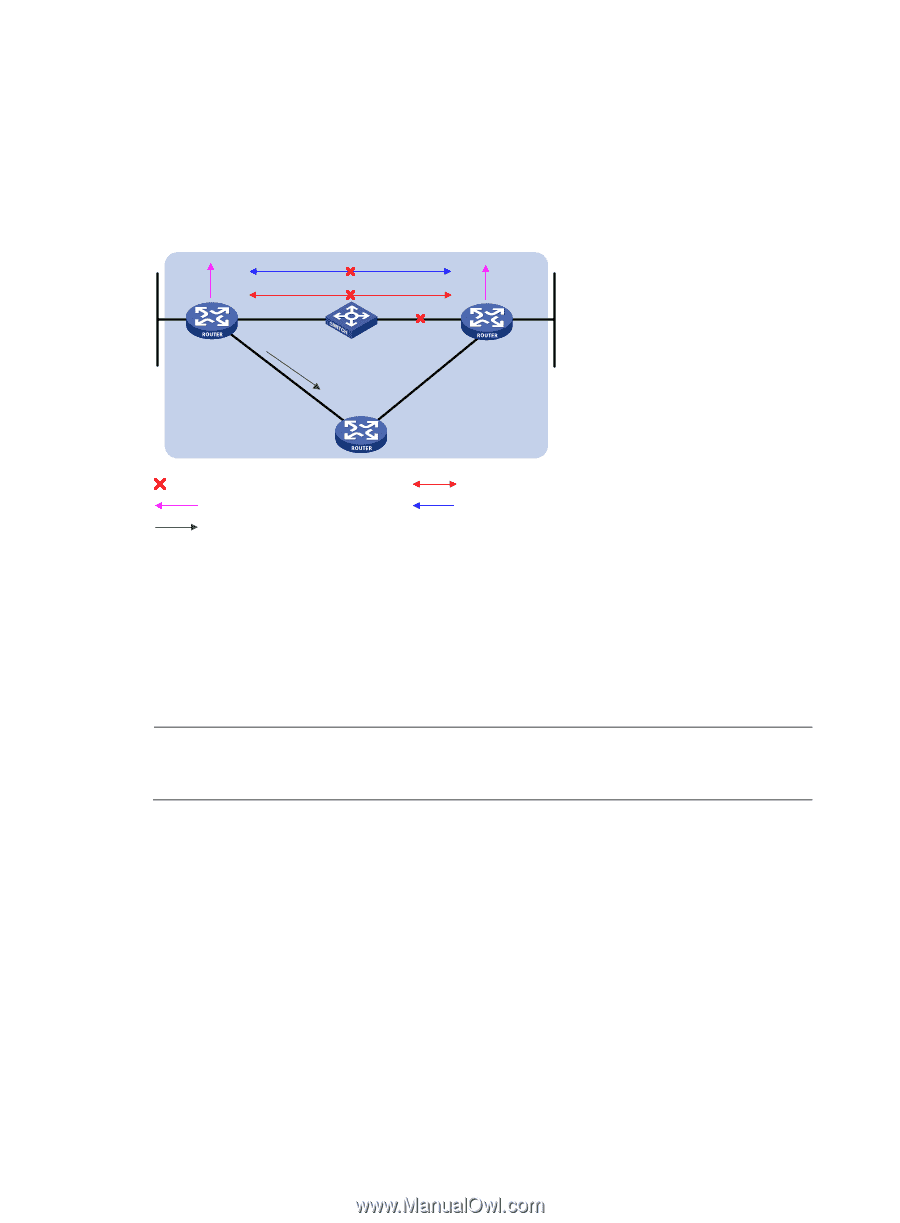
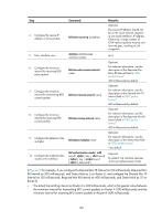
The process of BFD session establishment is as follows: 1. A protocol sends hello messages to discover neighbors and establish neighborships. 2. After establishing neighborships, the protocol notifies BFD of the neighbor information, including destination and source addresses. 3. BFD uses the information to establish BFD sessions. Figure 46 BFD fault detection (on OSPF routers) 4 3 2 3 Router A 5 1 Router B Fault BFD notifies the OSPF link failure Backup link BFD neighbors OSPF neighbors The process of BFD fault detection is as follows: 1. BFD detects a link failure. 2. BFD clears the neighbor session. 3. BFD notifies the protocol of the failure. 4. The protocol terminates the neighborship on the link. 5. If a backup link is available, the protocol will use it to forward packets. NOTE: No detection time resolution is defined in the BFD draft. Most devices supporting BFD provide detection measured in milliseconds. BFD detection methods • Single-hop detection-Detects the IP connectivity between two directly connected systems. • Multi-hop detection-Detects any of the paths between two systems. These paths have multiple hops and may be overlapped. • Bidirectional detection-Sends detection packets at two sides of a bidirectional link to detect the bidirectional link status, finding link failures in milliseconds. (BFD LSP detection is a special case in which BFD control packets are sent in one direction, and the peer device reports the link status through other links.) BFD session modes • Control packet mode-Both ends of the link exchange BFD control packets to monitor link status. • Echo mode-One end of the link sends Echo packets to the other end, which then forwards the packets back to the originating end, monitoring link status in both directions. 176
-
 1
1 -
2
-
3
-
4
-
5
-
6
-
7
-
8
-
9
-
10
-
11
-
12
-
13
-
14
-
15
-
16
-
17
-
18
-
19
-
20
-
21
-
22
-
23
-
24
-
25
-
26
-
27
-
28
-
29
-
30
-
31
-
32
-
33
-
34
-
35
-
36
-
37
-
38
-
39
-
40
-
41
-
42
-
43
-
44
-
45
-
46
-
47
-
48
-
49
-
50
-
51
-
52
-
53
-
54
-
55
-
56
-
57
-
58
-
59
-
60
-
61
-
62
-
63
-
64
-
65
-
66
-
67
-
68
-
69
-
70
-
71
-
72
-
73
-
74
-
75
-
76
-
77
-
78
-
79
-
80
-
81
-
82
-
83
-
84
-
85
-
86
-
87
-
88
-
89
-
90
-
91
-
92
-
93
-
94
-
95
-
96
-
97
-
98
-
99
-
100
-
101
-
102
-
103
-
104
-
105
-
106
-
107
-
108
-
109
-
110
-
111
-
112
-
113
-
114
-
115
-
116
-
117
-
118
-
119
-
120
-
121
-
122
-
123
-
124
-
125
-
126
-
127
-
128
-
129
-
130
-
131
-
132
-
133
-
134
-
135
-
136
-
137
-
138
-
139
-
140
-
141
-
142
-
143
-
144
-
145
-
146
-
147
-
148
-
149
-
150
-
151
-
152
-
153
-
154
-
155
-
156
-
157
-
158
-
159
-
160
-
161
-
162
-
163
-
164
-
165
-
166
-
167
-
168
-
169
-
170
-
171
-
172
-
173
-
174
-
175
-
176
-
177
-
 178
178 -
 179
179 -
 180
180 -
 181
181 -
 182
182 -
 183
183 -
 184
184 -
 185
185 -
 186
186 -
 187
187 -
 188
188 -
189
-
190
-
191
-
192
-
193
-
194
-
195
-
196
-
197
-
198
-
199
-
200
-
201
-
202
-
203
-
204
-
205
-
206
-
207
-
208
-
209
-
210
-
211
-
212
-
213
-
214
-
215
-
216
-
217
-
218
-
219
-
220
-
221
-
222
 |
 |