HP 6125G HP 6125G & 6125G/XG Blade Switches High Availability Configur - Page 64
Configuration procedure, Configuring protected VLANs
 |
View all HP 6125G manuals
Add to My Manuals
Save this manual to your list of manuals |
Page 64 highlights
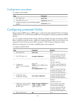
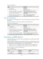
Configuration procedure To configure control VLANs: Step Command 1. Enter system view. system-view 2. Enter RRPP domain view. rrpp domain domain-id 3. Configure the primary control VLAN for the RRPP domain. control-vlan vlan-id Configuring protected VLANs Before configuring RRPP rings in an RRPP domain, configure the same protected VLANs for all nodes in the RRPP domain first. All VLANs that the RRPP ports are assigned to should be protected by the RRPP domains. You can configure protected VLANs through referencing Multiple Spanning Tree Instances (MSTIs). Before configuring protected VLANs, configure the mappings between MSTIs and the VLANs to be protected. For more information about MSTIs, see Layer 2-LAN Switching Configuration Guide. Perform this configuration on all nodes in the RRPP domain to be configured. To configure protected VLANs: Step 1. Enter system view. Command system-view Remarks N/A 2. Enter MST region view. stp region-configuration For more information about the command, see Layer 2-LAN Switching Command Reference. 3. Configure the VLAN-to-instance mapping table. Approach 1: instance instance-id vlan vlan-list Approach 2: vlan-mapping modulo modulo Optional. Use either approach. All VLANs in an MST region are mapped to MSTI 0 (the CIST) by default. For more information about the commands, see Layer 2-LAN Switching Command Reference. 4. Activate MST region configuration manually. active region-configuration For more information about the command, see Layer 2-LAN Switching Command Reference. Optional. Available in any view. 5. Display the currently activated display stp region-configuration [ | The command output includes configuration information of { begin | exclude | include } VLAN-to-instance mappings. the MST region. regular-expression ] For more information about the command, see Layer 2-LAN Switching Command Reference. 6. Return to system view. quit N/A 57
-
 1
1 -
2
-
3
-
4
-
5
-
6
-
7
-
8
-
9
-
10
-
11
-
12
-
13
-
14
-
15
-
16
-
17
-
18
-
19
-
20
-
21
-
22
-
23
-
24
-
25
-
26
-
27
-
28
-
29
-
30
-
31
-
32
-
33
-
34
-
35
-
36
-
37
-
38
-
39
-
40
-
41
-
42
-
43
-
44
-
45
-
46
-
47
-
48
-
49
-
50
-
51
-
52
-
53
-
54
-
55
-
56
-
57
-
58
-
 59
59 -
 60
60 -
 61
61 -
 62
62 -
 63
63 -
 64
64 -
 65
65 -
 66
66 -
 67
67 -
 68
68 -
 69
69 -
70
-
71
-
72
-
73
-
74
-
75
-
76
-
77
-
78
-
79
-
80
-
81
-
82
-
83
-
84
-
85
-
86
-
87
-
88
-
89
-
90
-
91
-
92
-
93
-
94
-
95
-
96
-
97
-
98
-
99
-
100
-
101
-
102
-
103
-
104
-
105
-
106
-
107
-
108
-
109
-
110
-
111
-
112
-
113
-
114
-
115
-
116
-
117
-
118
-
119
-
120
-
121
-
122
-
123
-
124
-
125
-
126
-
127
-
128
-
129
-
130
-
131
-
132
-
133
-
134
-
135
-
136
-
137
-
138
-
139
-
140
-
141
-
142
-
143
-
144
-
145
-
146
-
147
-
148
-
149
-
150
-
151
-
152
-
153
-
154
-
155
-
156
-
157
-
158
-
159
-
160
-
161
-
162
-
163
-
164
-
165
-
166
-
167
-
168
-
169
-
170
-
171
-
172
-
173
-
174
-
175
-
176
-
177
-
178
-
179
-
180
-
181
-
182
-
183
-
184
-
185
-
186
-
187
-
188
-
189
-
190
-
191
-
192
-
193
-
194
-
195
-
196
-
197
-
198
-
199
-
200
-
201
-
202
-
203
-
204
-
205
-
206
-
207
-
208
-
209
-
210
-
211
-
212
-
213
-
214
-
215
-
216
-
217
-
218
-
219
-
220
-
221
-
222
 |
 |