HP 6125G HP 6125G & 6125G/XG Blade Switches High Availability Configur - Page 58
Link down alarm mechanism, Ring recovery
 |
View all HP 6125G manuals
Add to My Manuals
Save this manual to your list of manuals |
Page 58 highlights
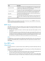
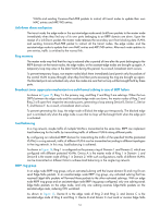
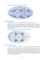
VLANs and sending Common-Flush-FDB packets to instruct all transit nodes to update their own MAC entries and ARP/ND entries. Link down alarm mechanism The transit node, the edge node or the assistant-edge node sends Link-Down packets to the master node immediately when they find any of its own ports belonging to an RRPP domain are down. Upon the receipt of a Link-Down packet, the master node releases the secondary port from blocking data VLANs and sending Common-Flush-FDB packet to instruct all the transit nodes, the edge nodes, and the assistant-edge nodes to update their own MAC entries and ARP/ND entries. After each node updates its own entries, traffic is switched to the normal link. Ring recovery The master node may find that the ring is restored after a period of time after the ports belonging to the RRPP domain on the transit nodes, the edge nodes, or the assistant-edge nodes are brought up again. A temporary loop may arise in the data VLAN during this period. As a result, broadcast storm occurs. To prevent temporary loops, non-master nodes block them immediately (and permit only the packets of the control VLAN to pass through) when they find their ports accessing the ring are brought up again. The blocked ports are activated only when the nodes are sure that no loop will be brought forth by these ports. Broadcast storm suppression mechanism in a multi-homed subring in case of SRPT failure As shown in Figure 15, Ring 1 is the primary ring, and Ring 2 and Ring 3 are subrings. When the two SRPTs between the edge node and the assistant-edge node are down, the master nodes of Ring 2 and Ring 3 will open their respective secondary ports, generating a loop among Device B, Device C, Device E, and Device F. As a result, a broadcast storm occurs. To prevent generating this loop, the edge node will block the edge port temporarily. The blocked edge port is activated only when the edge node is sure that no loop will be brought forth when the edge port is activated. Load balancing In a ring network, maybe traffic of multiple VLANs is transmitted at the same time. RRPP can implement load balancing for the traffic by transmitting traffic of different VLANs along different paths. By configuring an individual RRPP domain for transmitting the traffic of the specified VLANs (protected VLANs) in a ring network, traffic of different VLANs can be transmitted according to different topologies in the ring network. In this way, load balancing is achieved. As shown in Figure 16, Ring 1 is configured as the primary ring of Domain 1 and Domain 2, which are configured with different protected VLANs. Device A is the master node of Ring 1 in Domain 1, and Device B is the master node of Ring 1 in Domain 2. With such configurations, traffic of different VLANs can be transmitted on different links to achieve load balancing in the single-ring network. RRPP ring group In an edge node RRPP ring group, only an activated subring with the lowest domain ID and ring ID can send Edge-Hello packets. In an assistant-edge node RRPP ring group, any activated subring that has received Edge-Hello packets will forward these packets to the other activated subrings. With an edge node RRPP ring group and an assistant-edge node RRPP ring group configured, only one subring sends Edge-Hello packets on the edge node, and only one subring receives Edge-Hello packets on the assistant-edge node, reducing CPU workload. As shown in Figure 15, Device B is the edge node of Ring 2 and Ring 3, and Device C is the assistant-edge node of Ring 2 and Ring 3. Device B and Device C must send or receive Edge-Hello 51
-
 1
1 -
2
-
3
-
4
-
5
-
6
-
7
-
8
-
9
-
10
-
11
-
12
-
13
-
14
-
15
-
16
-
17
-
18
-
19
-
20
-
21
-
22
-
23
-
24
-
25
-
26
-
27
-
28
-
29
-
30
-
31
-
32
-
33
-
34
-
35
-
36
-
37
-
38
-
39
-
40
-
41
-
42
-
43
-
44
-
45
-
46
-
47
-
48
-
49
-
50
-
51
-
52
-
 53
53 -
 54
54 -
 55
55 -
 56
56 -
 57
57 -
 58
58 -
 59
59 -
 60
60 -
 61
61 -
 62
62 -
 63
63 -
64
-
65
-
66
-
67
-
68
-
69
-
70
-
71
-
72
-
73
-
74
-
75
-
76
-
77
-
78
-
79
-
80
-
81
-
82
-
83
-
84
-
85
-
86
-
87
-
88
-
89
-
90
-
91
-
92
-
93
-
94
-
95
-
96
-
97
-
98
-
99
-
100
-
101
-
102
-
103
-
104
-
105
-
106
-
107
-
108
-
109
-
110
-
111
-
112
-
113
-
114
-
115
-
116
-
117
-
118
-
119
-
120
-
121
-
122
-
123
-
124
-
125
-
126
-
127
-
128
-
129
-
130
-
131
-
132
-
133
-
134
-
135
-
136
-
137
-
138
-
139
-
140
-
141
-
142
-
143
-
144
-
145
-
146
-
147
-
148
-
149
-
150
-
151
-
152
-
153
-
154
-
155
-
156
-
157
-
158
-
159
-
160
-
161
-
162
-
163
-
164
-
165
-
166
-
167
-
168
-
169
-
170
-
171
-
172
-
173
-
174
-
175
-
176
-
177
-
178
-
179
-
180
-
181
-
182
-
183
-
184
-
185
-
186
-
187
-
188
-
189
-
190
-
191
-
192
-
193
-
194
-
195
-
196
-
197
-
198
-
199
-
200
-
201
-
202
-
203
-
204
-
205
-
206
-
207
-
208
-
209
-
210
-
211
-
212
-
213
-
214
-
215
-
216
-
217
-
218
-
219
-
220
-
221
-
222
 |
 |