HP 6125G HP 6125G & 6125G/XG Blade Switches High Availability Configur - Page 14
Link monitoring
 |
View all HP 6125G manuals
Add to My Manuals
Save this manual to your list of manuals |
Page 14 highlights
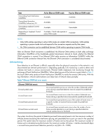
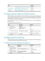
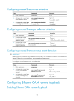
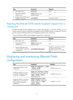
Item Transmitting Event Notification OAMPDUs Transmitting Information OAMPDUs without any TLV Transmitting Loopback Control OAMPDUs Responding to Loopback Control OAMPDUs Active Ethernet OAM mode Available Passive Ethernet OAM mode Available Available Available Available Unavailable Available-if both sides operate in active OAM mode Available NOTE: • Only OAM entities operating in active OAM mode can initiate OAM connections. OAM entities operating in passive mode wait and respond to the connection requests sent by their peers. • No OAM connection can be established between OAM entities operating in passive OAM mode. After an Ethernet OAM connection is established, the Ethernet OAM entities on both sides exchange Information OAMPDUs at the handshake packet transmission interval to check whether the Ethernet OAM connection is normal. If an Ethernet OAM entity receives no Information OAMPDU within the Ethernet OAM connection timeout time, the Ethernet OAM connection is considered disconnected. Link monitoring Error detection in an Ethernet is difficult, especially when the physical connection in the network is not disconnected but network performance is degrading gradually. Link monitoring is used to detect and indicate link faults in various environments. Ethernet OAM implements link monitoring through the exchange of Event Notification OAMPDUs. When detecting one of the link error events listed in Table 7, the local OAM entity sends an Event Notification OAMPDU to notify the remote OAM entity. With the log information, network administrators can keep track of network status promptly. Table 7 Ethernet OAM link error events Ethernet OAM link events Errored symbol event Errored frame event Errored frame period event Errored frame seconds event Description An errored symbol event occurs when the number of detected symbol errors during a specified detection interval exceeds the predefined threshold. An errored frame event occurs when the number of detected error frames during a specified interval exceeds the predefined threshold. An errored frame period event occurs if the number of frame errors in a specific number of received frames exceeds the predefined threshold. An errored frame seconds event occurs when the number of error frame seconds detected on a port during a specified detection interval reaches the error threshold. The system transforms the period of detecting errored frame period events into the maximum number of 64-byte frames (excluding the interframe spacing and preamble) that a port can send in the specified period. The system takes the maximum number of frames sent as the period. The maximum number of frames sent is calculated using this formula: the maximum number of frames = interface bandwidth (bps) × errored frame period event detection period (in ms)/(64 × 8 × 1000). 7
-
 1
1 -
2
-
3
-
4
-
5
-
6
-
7
-
8
-
 9
9 -
 10
10 -
 11
11 -
 12
12 -
 13
13 -
 14
14 -
 15
15 -
 16
16 -
 17
17 -
 18
18 -
 19
19 -
20
-
21
-
22
-
23
-
24
-
25
-
26
-
27
-
28
-
29
-
30
-
31
-
32
-
33
-
34
-
35
-
36
-
37
-
38
-
39
-
40
-
41
-
42
-
43
-
44
-
45
-
46
-
47
-
48
-
49
-
50
-
51
-
52
-
53
-
54
-
55
-
56
-
57
-
58
-
59
-
60
-
61
-
62
-
63
-
64
-
65
-
66
-
67
-
68
-
69
-
70
-
71
-
72
-
73
-
74
-
75
-
76
-
77
-
78
-
79
-
80
-
81
-
82
-
83
-
84
-
85
-
86
-
87
-
88
-
89
-
90
-
91
-
92
-
93
-
94
-
95
-
96
-
97
-
98
-
99
-
100
-
101
-
102
-
103
-
104
-
105
-
106
-
107
-
108
-
109
-
110
-
111
-
112
-
113
-
114
-
115
-
116
-
117
-
118
-
119
-
120
-
121
-
122
-
123
-
124
-
125
-
126
-
127
-
128
-
129
-
130
-
131
-
132
-
133
-
134
-
135
-
136
-
137
-
138
-
139
-
140
-
141
-
142
-
143
-
144
-
145
-
146
-
147
-
148
-
149
-
150
-
151
-
152
-
153
-
154
-
155
-
156
-
157
-
158
-
159
-
160
-
161
-
162
-
163
-
164
-
165
-
166
-
167
-
168
-
169
-
170
-
171
-
172
-
173
-
174
-
175
-
176
-
177
-
178
-
179
-
180
-
181
-
182
-
183
-
184
-
185
-
186
-
187
-
188
-
189
-
190
-
191
-
192
-
193
-
194
-
195
-
196
-
197
-
198
-
199
-
200
-
201
-
202
-
203
-
204
-
205
-
206
-
207
-
208
-
209
-
210
-
211
-
212
-
213
-
214
-
215
-
216
-
217
-
218
-
219
-
220
-
221
-
222
 |
 |