HP 6125G HP 6125G & 6125G/XG Blade Switches High Availability Configur - Page 152
Configuration procedure
 |
View all HP 6125G manuals
Add to My Manuals
Save this manual to your list of manuals |
Page 152 highlights
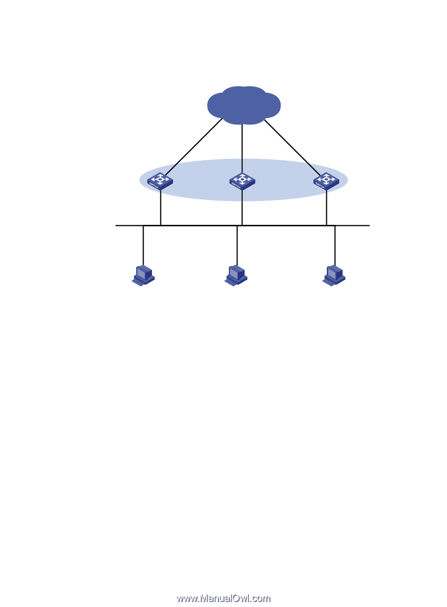
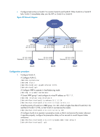
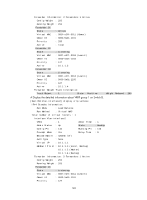
• Configure track entries on Switch C to monitor Switch A and Switch B. When Switch A or Switch B fails, Switch C immediately takes over the AVF on Switch A or Switch B. Figure 40 Network diagram Network Switch A Master Vlan-int3 AVF 1 Switch B Vlan-int3 Backup AVF 2 Vlan-int2 IP: 10.1.1.2/24 VIP: 10.1.1.1/24 Vlan-int2 IP: 10.1.1.3/24 VIP: 10.1.1.1/24 Switch C Vlan-int3 Backup AVF 3 Vlan-int2 IP: 10.1.1.4/24 VIP: 10.1.1.1/24 IP: 10.1.1.5/24 Gateway IP: 10.1.1.1/24 IP: 10.1.1.6/24 Gateway IP: 10.1.1.1/24 IP: 10.1.1.7/24 Gateway IP: 10.1.1.1/24 Host A Host B Host C Configuration procedure 1. Configure Switch A: # Configure VLAN 2. system-view [SwitchA] vlan 2 [SwitchA-vlan2] port gigabitethernet 1/0/5 [SwitchA-vlan2] quit # Configure VRRP to operate in load balancing mode. [SwitchA] vrrp mode load-balance # Create VRRP group 1 and configure its virtual IP address as 10.1.1.1. [SwitchA] interface vlan-interface 2 [SwitchA-Vlan-interface2] ip address 10.1.1.2 24 [SwitchA-Vlan-interface2] vrrp vrid 1 virtual-ip 10.1.1.1 # Set the priority of Switch A in VRRP group 1 to 120, which is higher than that of Switch B (110) and that of Switch C (100), so that Switch A can become the master. [SwitchA-Vlan-interface2] vrrp vrid 1 priority 120 # Configure Switch A to operate in preemptive mode, so that it can become the master whenever it operates properly; configure the preemption delay as five seconds to avoid frequent status switchover. [SwitchA-Vlan-interface2] vrrp vrid 1 preempt-mode timer delay 5 [SwitchA-Vlan-interface2] quit 145
-
 1
1 -
2
-
3
-
4
-
5
-
6
-
7
-
8
-
9
-
10
-
11
-
12
-
13
-
14
-
15
-
16
-
17
-
18
-
19
-
20
-
21
-
22
-
23
-
24
-
25
-
26
-
27
-
28
-
29
-
30
-
31
-
32
-
33
-
34
-
35
-
36
-
37
-
38
-
39
-
40
-
41
-
42
-
43
-
44
-
45
-
46
-
47
-
48
-
49
-
50
-
51
-
52
-
53
-
54
-
55
-
56
-
57
-
58
-
59
-
60
-
61
-
62
-
63
-
64
-
65
-
66
-
67
-
68
-
69
-
70
-
71
-
72
-
73
-
74
-
75
-
76
-
77
-
78
-
79
-
80
-
81
-
82
-
83
-
84
-
85
-
86
-
87
-
88
-
89
-
90
-
91
-
92
-
93
-
94
-
95
-
96
-
97
-
98
-
99
-
100
-
101
-
102
-
103
-
104
-
105
-
106
-
107
-
108
-
109
-
110
-
111
-
112
-
113
-
114
-
115
-
116
-
117
-
118
-
119
-
120
-
121
-
122
-
123
-
124
-
125
-
126
-
127
-
128
-
129
-
130
-
131
-
132
-
133
-
134
-
135
-
136
-
137
-
138
-
139
-
140
-
141
-
142
-
143
-
144
-
145
-
146
-
 147
147 -
 148
148 -
 149
149 -
 150
150 -
 151
151 -
 152
152 -
 153
153 -
 154
154 -
 155
155 -
 156
156 -
 157
157 -
158
-
159
-
160
-
161
-
162
-
163
-
164
-
165
-
166
-
167
-
168
-
169
-
170
-
171
-
172
-
173
-
174
-
175
-
176
-
177
-
178
-
179
-
180
-
181
-
182
-
183
-
184
-
185
-
186
-
187
-
188
-
189
-
190
-
191
-
192
-
193
-
194
-
195
-
196
-
197
-
198
-
199
-
200
-
201
-
202
-
203
-
204
-
205
-
206
-
207
-
208
-
209
-
210
-
211
-
212
-
213
-
214
-
215
-
216
-
217
-
218
-
219
-
220
-
221
-
222
 |
 |