HP 6125G HP 6125G & 6125G/XG Blade Switches High Availability Configur - Page 145
VRRP interface tracking configuration example, Network requirements, If Switch A operates properly
 |
View all HP 6125G manuals
Add to My Manuals
Save this manual to your list of manuals |
Page 145 highlights
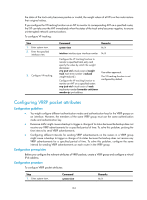
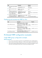
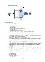
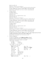
Preempt Mode : Yes Delay Time : 5 Auth Type : None Virtual IP : 202.38.160.111 Virtual MAC : 0000-5e00-0101 Master IP : 202.38.160.2 The output shows that when Switch A fails, Switch B becomes the master, and packets sent from Host A to Host B are forwarded by Switch B. # After Switch A resumes normal operation, use the display vrrp verbose command to display the detailed information about VRRP group 1 on Switch A. [SwitchA-Vlan-interface2] display vrrp verbose IPv4 Standby Information: Run Mode : Standard Run Method : Virtual MAC Total number of virtual routers : 1 Interface Vlan-interface2 VRID : 1 Adver Timer : 1 Admin Status : Up State : Master Config Pri : 110 Running Pri : 110 Preempt Mode : Yes Delay Time : 5 Auth Type : None Virtual IP : 202.38.160.111 Virtual MAC : 0000-5e00-0101 Master IP : 202.38.160.1 The output shows that after Switch A resumes normal operation, it becomes the master, and packets sent from host A to host B are forwarded by Switch A. VRRP interface tracking configuration example Network requirements • Host A wants to access Host B on the Internet, using 202.38.160.111/24 as its default gateway. • Switch A and Switch B belong to VRRP group 1 with the virtual IP address of 202.38.160.111/24. • If Switch A operates properly, packets sent from Host A to Host B are forwarded by Switch A. If VLAN-interface 3 through which Switch A connects to the Internet is not available, packets sent from Host A to Host B are forwarded by Switch B. • To prevent attacks to the VRRP group from illegal users by using spoofed packets, configure the authentication mode as plain text to authenticate the VRRP packets in VRRP group 1, and specify the authentication key as hello. 138
-
 1
1 -
2
-
3
-
4
-
5
-
6
-
7
-
8
-
9
-
10
-
11
-
12
-
13
-
14
-
15
-
16
-
17
-
18
-
19
-
20
-
21
-
22
-
23
-
24
-
25
-
26
-
27
-
28
-
29
-
30
-
31
-
32
-
33
-
34
-
35
-
36
-
37
-
38
-
39
-
40
-
41
-
42
-
43
-
44
-
45
-
46
-
47
-
48
-
49
-
50
-
51
-
52
-
53
-
54
-
55
-
56
-
57
-
58
-
59
-
60
-
61
-
62
-
63
-
64
-
65
-
66
-
67
-
68
-
69
-
70
-
71
-
72
-
73
-
74
-
75
-
76
-
77
-
78
-
79
-
80
-
81
-
82
-
83
-
84
-
85
-
86
-
87
-
88
-
89
-
90
-
91
-
92
-
93
-
94
-
95
-
96
-
97
-
98
-
99
-
100
-
101
-
102
-
103
-
104
-
105
-
106
-
107
-
108
-
109
-
110
-
111
-
112
-
113
-
114
-
115
-
116
-
117
-
118
-
119
-
120
-
121
-
122
-
123
-
124
-
125
-
126
-
127
-
128
-
129
-
130
-
131
-
132
-
133
-
134
-
135
-
136
-
137
-
138
-
139
-
 140
140 -
 141
141 -
 142
142 -
 143
143 -
 144
144 -
 145
145 -
 146
146 -
 147
147 -
 148
148 -
 149
149 -
 150
150 -
151
-
152
-
153
-
154
-
155
-
156
-
157
-
158
-
159
-
160
-
161
-
162
-
163
-
164
-
165
-
166
-
167
-
168
-
169
-
170
-
171
-
172
-
173
-
174
-
175
-
176
-
177
-
178
-
179
-
180
-
181
-
182
-
183
-
184
-
185
-
186
-
187
-
188
-
189
-
190
-
191
-
192
-
193
-
194
-
195
-
196
-
197
-
198
-
199
-
200
-
201
-
202
-
203
-
204
-
205
-
206
-
207
-
208
-
209
-
210
-
211
-
212
-
213
-
214
-
215
-
216
-
217
-
218
-
219
-
220
-
221
-
222
 |
 |