HP 6125G HP 6125G & 6125G/XG Blade Switches High Availability Configur - Page 101
Configuring member ports for a smart link group, In smart link group view, In interface view
 |
View all HP 6125G manuals
Add to My Manuals
Save this manual to your list of manuals |
Page 101 highlights
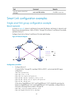
Step 1. Enter system view. Command system-view Remarks N/A 2. Enter MST region view. stp region-configuration For more information about the command, see Layer 2-LAN Switching Command Reference. 3. Configure the VLAN-to-instance mapping table. Approach 1: instance instance-id vlan vlan-list Approach 2: vlan-mapping modulo modulo Optional. Use either approach. All VLANs in an MST region are mapped to CIST (MSTI 0) by default. For more information about the commands, see Layer 2-LAN Switching Command Reference. 4. Activate MST region configuration manually. active region-configuration For more information about the command, see Layer 2-LAN Switching Command Reference. Optional. Available in any view. 5. Display the currently activated display stp region-configuration [ | You can view the VLANs mapped configuration information of { begin | exclude | include } to the MSTIs. the MST region. regular-expression ] For more information about the command, see Layer 2-LAN Switching Command Reference. 6. Return to system view. 7. Create a smart link group, and enter smart link group view. quit smart-link group group-id N/A N/A 8. Configure protected VLANs for the smart link group. protected-vlan reference-instance instance-id-list By default, no protected VLAN is configured for a smart link group. Configuring member ports for a smart link group You can configure member ports for a smart link group either in smart link group view or in interface view. The configurations made in these two views have the same effect. In smart link group view To configure member ports for a smart link group in smart link group view: Step 1. Enter system view. 2. Create a smart link group, and enter smart link group view. 3. Configure member ports for a smart link group. Command system-view smart-link group group-id port interface-type interface-number { master | slave } In interface view To configure member ports for a smart link group in interface view: 94
-
 1
1 -
2
-
3
-
4
-
5
-
6
-
7
-
8
-
9
-
10
-
11
-
12
-
13
-
14
-
15
-
16
-
17
-
18
-
19
-
20
-
21
-
22
-
23
-
24
-
25
-
26
-
27
-
28
-
29
-
30
-
31
-
32
-
33
-
34
-
35
-
36
-
37
-
38
-
39
-
40
-
41
-
42
-
43
-
44
-
45
-
46
-
47
-
48
-
49
-
50
-
51
-
52
-
53
-
54
-
55
-
56
-
57
-
58
-
59
-
60
-
61
-
62
-
63
-
64
-
65
-
66
-
67
-
68
-
69
-
70
-
71
-
72
-
73
-
74
-
75
-
76
-
77
-
78
-
79
-
80
-
81
-
82
-
83
-
84
-
85
-
86
-
87
-
88
-
89
-
90
-
91
-
92
-
93
-
94
-
95
-
 96
96 -
 97
97 -
 98
98 -
 99
99 -
 100
100 -
 101
101 -
 102
102 -
 103
103 -
 104
104 -
 105
105 -
 106
106 -
107
-
108
-
109
-
110
-
111
-
112
-
113
-
114
-
115
-
116
-
117
-
118
-
119
-
120
-
121
-
122
-
123
-
124
-
125
-
126
-
127
-
128
-
129
-
130
-
131
-
132
-
133
-
134
-
135
-
136
-
137
-
138
-
139
-
140
-
141
-
142
-
143
-
144
-
145
-
146
-
147
-
148
-
149
-
150
-
151
-
152
-
153
-
154
-
155
-
156
-
157
-
158
-
159
-
160
-
161
-
162
-
163
-
164
-
165
-
166
-
167
-
168
-
169
-
170
-
171
-
172
-
173
-
174
-
175
-
176
-
177
-
178
-
179
-
180
-
181
-
182
-
183
-
184
-
185
-
186
-
187
-
188
-
189
-
190
-
191
-
192
-
193
-
194
-
195
-
196
-
197
-
198
-
199
-
200
-
201
-
202
-
203
-
204
-
205
-
206
-
207
-
208
-
209
-
210
-
211
-
212
-
213
-
214
-
215
-
216
-
217
-
218
-
219
-
220
-
221
-
222
 |
 |