HP 6125G HP 6125G & 6125G/XG Blade Switches High Availability Configur - Page 119
Configuring VRRP, VRRP overview
 |
View all HP 6125G manuals
Add to My Manuals
Save this manual to your list of manuals |
Page 119 highlights
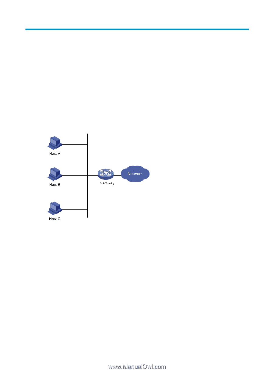
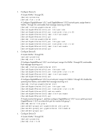
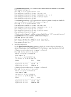
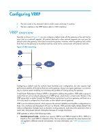
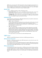
Configuring VRRP • The term router in this document refers to both routers and Layer 3 switches. • The term interface in the VRRP feature refers to VLAN interfaces. VRRP overview Typically, as shown in Figure 27, you can configure a default route with the gateway as the next hop for every host on a network segment. All packets destined to other network segments are sent over the default route to the gateway, which then forwards the packets. However, when the gateway fails, all the hosts that use the gateway as the default next-hop router fail to communicate with external networks. Figure 27 LAN networking Configuring a default route for network hosts facilitates your configuration, but also requires high performance stability of the device that acts as the gateway. Using more egress gateways is a common way to improve system reliability, but introduces the problem of routing among the egresses. Virtual Router Redundancy Protocol (VRRP) is designed to address this problem. VRRP adds a group of routers that can act as network gateways to a VRRP group, which forms a virtual router. Routers in the VRRP group elect a master through the VRRP election mechanism to act as a gateway, and hosts on a LAN only need to configure the virtual router as their default network gateway. VRRP is an error-tolerant protocol, which improves the network reliability and simplifies configurations on hosts. On a multicast and broadcast LAN such as Ethernet, VRRP provides highly reliable default links without configuration changes (such as dynamic routing protocols, route discovery protocols) when a router fails, and prevent network interruption because of a single link failure. VRRP operates in either of the following modes: • Standard protocol mode-Includes two versions VRRPv2 and VRRPv3 based on RFCs. VRRPv2 is based on IPv4, and VRRPv3 is based on IPv6. The two versions implement the same functions but are applied in different network environments. For more information, see "VRRP standard protocol mode." 112
-
 1
1 -
2
-
3
-
4
-
5
-
6
-
7
-
8
-
9
-
10
-
11
-
12
-
13
-
14
-
15
-
16
-
17
-
18
-
19
-
20
-
21
-
22
-
23
-
24
-
25
-
26
-
27
-
28
-
29
-
30
-
31
-
32
-
33
-
34
-
35
-
36
-
37
-
38
-
39
-
40
-
41
-
42
-
43
-
44
-
45
-
46
-
47
-
48
-
49
-
50
-
51
-
52
-
53
-
54
-
55
-
56
-
57
-
58
-
59
-
60
-
61
-
62
-
63
-
64
-
65
-
66
-
67
-
68
-
69
-
70
-
71
-
72
-
73
-
74
-
75
-
76
-
77
-
78
-
79
-
80
-
81
-
82
-
83
-
84
-
85
-
86
-
87
-
88
-
89
-
90
-
91
-
92
-
93
-
94
-
95
-
96
-
97
-
98
-
99
-
100
-
101
-
102
-
103
-
104
-
105
-
106
-
107
-
108
-
109
-
110
-
111
-
112
-
113
-
 114
114 -
 115
115 -
 116
116 -
 117
117 -
 118
118 -
 119
119 -
 120
120 -
 121
121 -
 122
122 -
 123
123 -
 124
124 -
125
-
126
-
127
-
128
-
129
-
130
-
131
-
132
-
133
-
134
-
135
-
136
-
137
-
138
-
139
-
140
-
141
-
142
-
143
-
144
-
145
-
146
-
147
-
148
-
149
-
150
-
151
-
152
-
153
-
154
-
155
-
156
-
157
-
158
-
159
-
160
-
161
-
162
-
163
-
164
-
165
-
166
-
167
-
168
-
169
-
170
-
171
-
172
-
173
-
174
-
175
-
176
-
177
-
178
-
179
-
180
-
181
-
182
-
183
-
184
-
185
-
186
-
187
-
188
-
189
-
190
-
191
-
192
-
193
-
194
-
195
-
196
-
197
-
198
-
199
-
200
-
201
-
202
-
203
-
204
-
205
-
206
-
207
-
208
-
209
-
210
-
211
-
212
-
213
-
214
-
215
-
216
-
217
-
218
-
219
-
220
-
221
-
222
 |
 |