HP 6125G HP 6125G & 6125G/XG Blade Switches High Availability Configur - Page 204
Con VRRP on Switch
 |
View all HP 6125G manuals
Add to My Manuals
Save this manual to your list of manuals |
Page 204 highlights
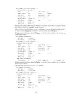
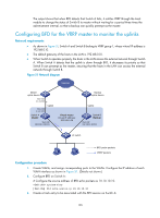
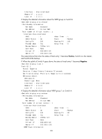
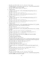
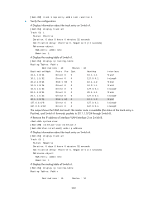
# Create track entry 1 to be associated with the BFD session to check whether the uplink device with the IP address 1.1.1.2 is reachable. [SwitchA] track 1 bfd echo interface vlan-interface 3 remote ip 1.1.1.2 local ip 1.1.1.1 4. Configure VRRP on Switch A: # Create VRRP group 1, and configure the virtual IP address of the group as 192.168.0.10. Configure the priority of Switch A in VRRP group 1 as 110. Configure VRRP group 1 to monitor the status of track entry 1. When the status of the track entry becomes Negative, the priority of Switch A decreases by 20. [SwitchA] interface vlan-interface 2 [SwitchA-Vlan-interface2] vrrp vrid 1 virtual-ip 192.168.0.10 [SwitchA-Vlan-interface2] vrrp vrid 1 priority 110 [SwitchA-Vlan-interface2] vrrp vrid 1 track 1 reduced 20 [SwitchA-Vlan-interface2] return 5. Configure VRRP on Switch B: # Create VRRP group 1, and configure the virtual IP address of the group as 192.168.0.10. system-view [SwitchB] interface vlan-interface 2 [SwitchB-Vlan-interface2] vrrp vrid 1 virtual-ip 192.168.0.10 [SwitchB-Vlan-interface2] return 6. Verify the configuration: # Display the detailed information about the VRRP group on Switch A. display vrrp verbose IPv4 Standby Information: Run Mode : Standard Run Method : Virtual MAC Total number of virtual routers : 1 Interface Vlan-interface2 VRID : 1 Adver Timer : 1 Admin Status : Up State : Master Config Pri : 110 Running Pri : 110 Preempt Mode : Yes Delay Time : 0 Auth Type : None Virtual IP : 192.168.0.10 Virtual MAC : 0000-5e00-0101 Master IP : 192.168.0.101 VRRP Track Information: Track Object : 1 State : Positive Pri Reduced : 20 # Display the information about track entry 1 on Switch A. display track 1 Track ID: 1 Status: Positive Duration: 0 days 0 hours 0 minutes 32 seconds Notification delay: Positive 0, Negative 0 (in seconds) Reference object: BFD session: Packet type: Echo 197
-
 1
1 -
2
-
3
-
4
-
5
-
6
-
7
-
8
-
9
-
10
-
11
-
12
-
13
-
14
-
15
-
16
-
17
-
18
-
19
-
20
-
21
-
22
-
23
-
24
-
25
-
26
-
27
-
28
-
29
-
30
-
31
-
32
-
33
-
34
-
35
-
36
-
37
-
38
-
39
-
40
-
41
-
42
-
43
-
44
-
45
-
46
-
47
-
48
-
49
-
50
-
51
-
52
-
53
-
54
-
55
-
56
-
57
-
58
-
59
-
60
-
61
-
62
-
63
-
64
-
65
-
66
-
67
-
68
-
69
-
70
-
71
-
72
-
73
-
74
-
75
-
76
-
77
-
78
-
79
-
80
-
81
-
82
-
83
-
84
-
85
-
86
-
87
-
88
-
89
-
90
-
91
-
92
-
93
-
94
-
95
-
96
-
97
-
98
-
99
-
100
-
101
-
102
-
103
-
104
-
105
-
106
-
107
-
108
-
109
-
110
-
111
-
112
-
113
-
114
-
115
-
116
-
117
-
118
-
119
-
120
-
121
-
122
-
123
-
124
-
125
-
126
-
127
-
128
-
129
-
130
-
131
-
132
-
133
-
134
-
135
-
136
-
137
-
138
-
139
-
140
-
141
-
142
-
143
-
144
-
145
-
146
-
147
-
148
-
149
-
150
-
151
-
152
-
153
-
154
-
155
-
156
-
157
-
158
-
159
-
160
-
161
-
162
-
163
-
164
-
165
-
166
-
167
-
168
-
169
-
170
-
171
-
172
-
173
-
174
-
175
-
176
-
177
-
178
-
179
-
180
-
181
-
182
-
183
-
184
-
185
-
186
-
187
-
188
-
189
-
190
-
191
-
192
-
193
-
194
-
195
-
196
-
197
-
198
-
 199
199 -
 200
200 -
 201
201 -
 202
202 -
 203
203 -
 204
204 -
 205
205 -
 206
206 -
 207
207 -
 208
208 -
 209
209 -
210
-
211
-
212
-
213
-
214
-
215
-
216
-
217
-
218
-
219
-
220
-
221
-
222
 |
 |