HP 6125G HP 6125G & 6125G/XG Blade Switches High Availability Configur - Page 125
VRRP load balancing mode, Overview
 |
View all HP 6125G manuals
Add to My Manuals
Save this manual to your list of manuals |
Page 125 highlights
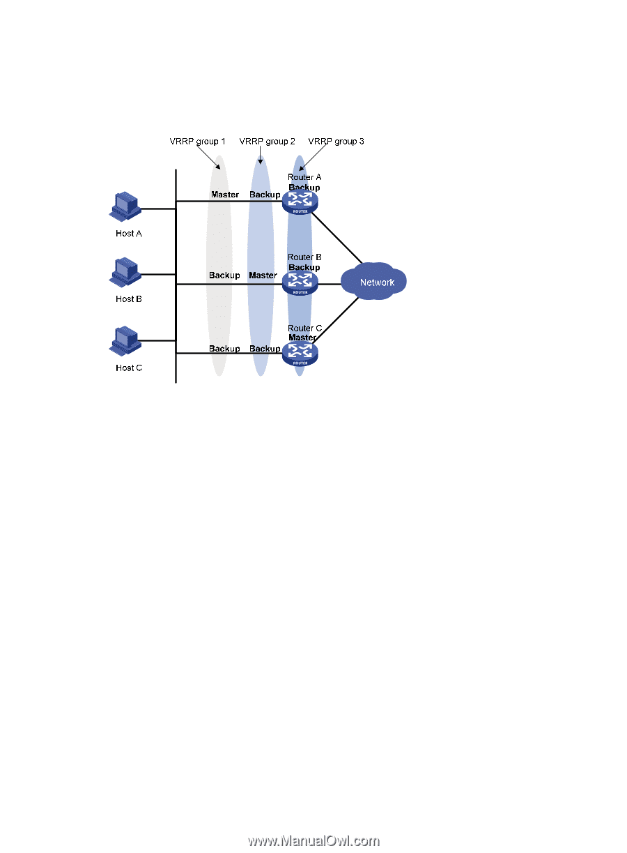
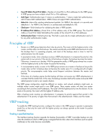
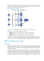
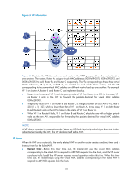
In load sharing mode, multiple routers provide services simultaneously. This mode requires two or more VRRP groups, each of which comprises a master and one or more backups. The masters of the VRRP groups are assumed by different routers, as shown in Figure 32. Figure 32 VRRP in load sharing mode A router can be in multiple VRRP groups and hold a different priority in a different group. As shown in Figure 32, the following VRRP groups are present: • VRRP group 1-Router A is the master; Router B and Router C are the backups. • VRRP group 2-Router B is the master; Router A and Router C are the backups. • VRRP group 3-Router C is the master; Router A and Router B are the backups. For load sharing among Router A, Router B, and Router C, hosts on the LAN need to be configured to use VRRP group 1, 2, and 3 as the default gateways. When you configure VRRP priorities, make sure that each router holds such a priority in each VRRP group that it will take the expected role in the group. VRRP load balancing mode Overview When VRRP is operating in standard protocol mode, only the master can forward packets and the backups are in the state of listening. You can create multiple VRRP groups to share the load among multiple routers, but hosts on the LAN need to be configured with different gateways, thus making the configuration complicated. In load balancing mode, VRRP provides load balancing in addition to virtual gateway redundancy by mapping a virtual IP address to multiple virtual MAC addresses to assign each router in a VRRP group one virtual MAC address. In this way, each router in this VRRP group can respond to ARP requests (in an IPv4 network) or ND requests (in an IPv6 network) from corresponding hosts, so that different hosts can send packets to different routers, and each router in the VRRP group can forward packets. In load 118
-
 1
1 -
2
-
3
-
4
-
5
-
6
-
7
-
8
-
9
-
10
-
11
-
12
-
13
-
14
-
15
-
16
-
17
-
18
-
19
-
20
-
21
-
22
-
23
-
24
-
25
-
26
-
27
-
28
-
29
-
30
-
31
-
32
-
33
-
34
-
35
-
36
-
37
-
38
-
39
-
40
-
41
-
42
-
43
-
44
-
45
-
46
-
47
-
48
-
49
-
50
-
51
-
52
-
53
-
54
-
55
-
56
-
57
-
58
-
59
-
60
-
61
-
62
-
63
-
64
-
65
-
66
-
67
-
68
-
69
-
70
-
71
-
72
-
73
-
74
-
75
-
76
-
77
-
78
-
79
-
80
-
81
-
82
-
83
-
84
-
85
-
86
-
87
-
88
-
89
-
90
-
91
-
92
-
93
-
94
-
95
-
96
-
97
-
98
-
99
-
100
-
101
-
102
-
103
-
104
-
105
-
106
-
107
-
108
-
109
-
110
-
111
-
112
-
113
-
114
-
115
-
116
-
117
-
118
-
119
-
 120
120 -
 121
121 -
 122
122 -
 123
123 -
 124
124 -
 125
125 -
 126
126 -
 127
127 -
 128
128 -
 129
129 -
 130
130 -
131
-
132
-
133
-
134
-
135
-
136
-
137
-
138
-
139
-
140
-
141
-
142
-
143
-
144
-
145
-
146
-
147
-
148
-
149
-
150
-
151
-
152
-
153
-
154
-
155
-
156
-
157
-
158
-
159
-
160
-
161
-
162
-
163
-
164
-
165
-
166
-
167
-
168
-
169
-
170
-
171
-
172
-
173
-
174
-
175
-
176
-
177
-
178
-
179
-
180
-
181
-
182
-
183
-
184
-
185
-
186
-
187
-
188
-
189
-
190
-
191
-
192
-
193
-
194
-
195
-
196
-
197
-
198
-
199
-
200
-
201
-
202
-
203
-
204
-
205
-
206
-
207
-
208
-
209
-
210
-
211
-
212
-
213
-
214
-
215
-
216
-
217
-
218
-
219
-
220
-
221
-
222
 |
 |