HP 6125G HP 6125G & 6125G/XG Blade Switches High Availability Configur - Page 207
Network diagram
 |
View all HP 6125G manuals
Add to My Manuals
Save this manual to your list of manuals |
Page 207 highlights
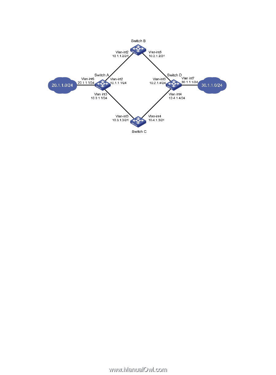
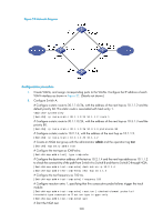
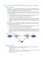
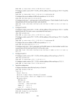
Figure 52 Network diagram Configuration procedure 1. Create VLANs, and assign corresponding ports to the VLANs. Configure the IP address of each VLAN interface as shown in Figure 52. (Details not shown.) 2. Configure Switch A: # Configure a static route to 30.1.1.0/24, with the address of the next hop as 10.1.1.2 and the default priority 60. This static route is associated with track entry 1. system-view [SwitchA] ip route-static 30.1.1.0 24 10.1.1.2 track 1 # Configure a static route to 30.1.1.0/24, with the address of the next hop as 10.3.1.3 and the priority 80. [SwitchA] ip route-static 30.1.1.0 24 10.3.1.3 preference 80 # Configure a static route to 10.2.1.4, with the address of the next hop as 10.1.1.2. [SwitchA] ip route-static 10.2.1.4 24 10.1.1.2 # Create an NQA test group with the administrator admin and the operation tag test. [SwitchA] nqa entry admin test # Configure the test type as ICMP-echo. [SwitchA-nqa-admin-test] type icmp-echo # Configure the destination address of the test as 10.2.1.4 and the next hop address as 10.1.1.2 to check the connectivity of the path from Switch A to Switch B and then to Switch D through NQA. [SwitchA-nqa-admin-test-icmp-echo] destination ip 10.2.1.4 [SwitchA-nqa-admin-test-icmp-echo] next-hop 10.1.1.2 # Configure the test frequency as 100 ms. [SwitchA-nqa-admin-test-icmp-echo] frequency 100 # Configure reaction entry 1, specifying that five consecutive probe failures trigger the track module. [SwitchA-nqa-admin-test-icmp-echo] reaction 1 checked-element probe-fail threshold-type consecutive 5 action-type trigger-only [SwitchA-nqa-admin-test-icmp-echo] quit # Start the NQA test. 200
-
 1
1 -
2
-
3
-
4
-
5
-
6
-
7
-
8
-
9
-
10
-
11
-
12
-
13
-
14
-
15
-
16
-
17
-
18
-
19
-
20
-
21
-
22
-
23
-
24
-
25
-
26
-
27
-
28
-
29
-
30
-
31
-
32
-
33
-
34
-
35
-
36
-
37
-
38
-
39
-
40
-
41
-
42
-
43
-
44
-
45
-
46
-
47
-
48
-
49
-
50
-
51
-
52
-
53
-
54
-
55
-
56
-
57
-
58
-
59
-
60
-
61
-
62
-
63
-
64
-
65
-
66
-
67
-
68
-
69
-
70
-
71
-
72
-
73
-
74
-
75
-
76
-
77
-
78
-
79
-
80
-
81
-
82
-
83
-
84
-
85
-
86
-
87
-
88
-
89
-
90
-
91
-
92
-
93
-
94
-
95
-
96
-
97
-
98
-
99
-
100
-
101
-
102
-
103
-
104
-
105
-
106
-
107
-
108
-
109
-
110
-
111
-
112
-
113
-
114
-
115
-
116
-
117
-
118
-
119
-
120
-
121
-
122
-
123
-
124
-
125
-
126
-
127
-
128
-
129
-
130
-
131
-
132
-
133
-
134
-
135
-
136
-
137
-
138
-
139
-
140
-
141
-
142
-
143
-
144
-
145
-
146
-
147
-
148
-
149
-
150
-
151
-
152
-
153
-
154
-
155
-
156
-
157
-
158
-
159
-
160
-
161
-
162
-
163
-
164
-
165
-
166
-
167
-
168
-
169
-
170
-
171
-
172
-
173
-
174
-
175
-
176
-
177
-
178
-
179
-
180
-
181
-
182
-
183
-
184
-
185
-
186
-
187
-
188
-
189
-
190
-
191
-
192
-
193
-
194
-
195
-
196
-
197
-
198
-
199
-
200
-
201
-
 202
202 -
 203
203 -
 204
204 -
 205
205 -
 206
206 -
 207
207 -
 208
208 -
 209
209 -
 210
210 -
 211
211 -
 212
212 -
213
-
214
-
215
-
216
-
217
-
218
-
219
-
220
-
221
-
222
 |
 |