HP 6125G HP 6125G & 6125G/XG Blade Switches High Availability Configur - Page 203
Configuring BFD for the VRRP master to monitor the uplinks, Network requirements
 |
View all HP 6125G manuals
Add to My Manuals
Save this manual to your list of manuals |
Page 203 highlights
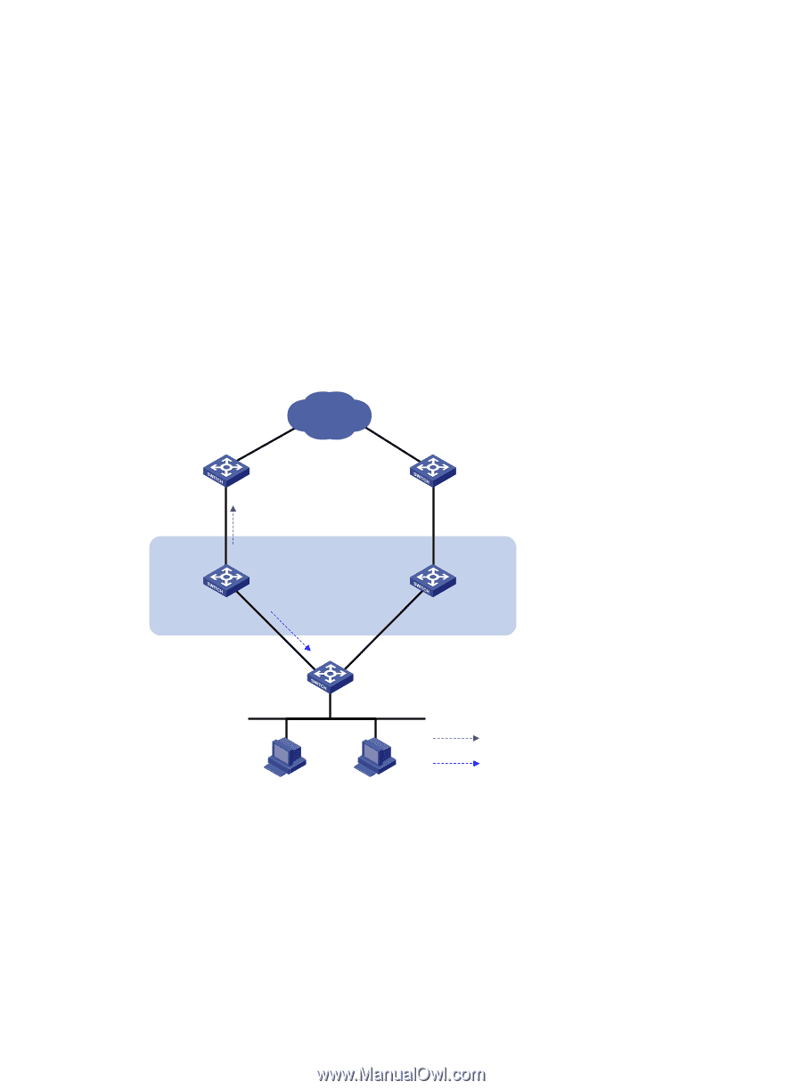
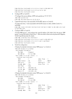
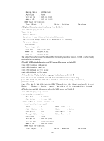
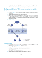
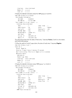
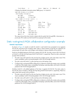
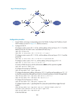
The output shows that when BFD detects that Switch A fails, it notifies VRRP through the track module to change the status of Switch B to master without waiting for a period three times the advertisement interval, so that a backup can quickly preempt as the master. Configuring BFD for the VRRP master to monitor the uplinks Network requirements • As shown in Figure 51, Switch A and Switch B belong to VRRP group 1, whose virtual IP address is 192.168.0.10. • The default gateway of the hosts in the LAN is 192.168.0.10. • When Switch A operates properly, the hosts in the LAN access the external network through Switch A. When Switch A detects that the uplink is down through BFD, it decreases its priority so that Switch B can preempt as the master, ensuring that the hosts in the LAN can access the external network through Switch B. Figure 51 Network diagram Internet Master uplink device Vlan-int3 1.1.1.2/24 Vlan-int3 1.1.1.1/24 Switch A Master Uplink Vlan-int2 192.168.0.101/24 Virtual router Virtual IP address: 192.168.0.10 Backup uplink device Uplink Switch B Backup Vlan-int2 192.168.0.102/24 L2 switch BFD probe packets VRRP packets Configuration procedure 1. Create VLANs, and assign corresponding ports to the VLANs. Configure the IP address of each VLAN interface as shown in Figure 51. (Details not shown.) 2. Configure BFD on Switch A: # Configure the source address of BFD echo packets as 10.10.10.10. system-view [SwitchA] bfd echo-source-ip 10.10.10.10 3. Create a track entry to be associated with the BFD session on Switch A: 196
-
 1
1 -
2
-
3
-
4
-
5
-
6
-
7
-
8
-
9
-
10
-
11
-
12
-
13
-
14
-
15
-
16
-
17
-
18
-
19
-
20
-
21
-
22
-
23
-
24
-
25
-
26
-
27
-
28
-
29
-
30
-
31
-
32
-
33
-
34
-
35
-
36
-
37
-
38
-
39
-
40
-
41
-
42
-
43
-
44
-
45
-
46
-
47
-
48
-
49
-
50
-
51
-
52
-
53
-
54
-
55
-
56
-
57
-
58
-
59
-
60
-
61
-
62
-
63
-
64
-
65
-
66
-
67
-
68
-
69
-
70
-
71
-
72
-
73
-
74
-
75
-
76
-
77
-
78
-
79
-
80
-
81
-
82
-
83
-
84
-
85
-
86
-
87
-
88
-
89
-
90
-
91
-
92
-
93
-
94
-
95
-
96
-
97
-
98
-
99
-
100
-
101
-
102
-
103
-
104
-
105
-
106
-
107
-
108
-
109
-
110
-
111
-
112
-
113
-
114
-
115
-
116
-
117
-
118
-
119
-
120
-
121
-
122
-
123
-
124
-
125
-
126
-
127
-
128
-
129
-
130
-
131
-
132
-
133
-
134
-
135
-
136
-
137
-
138
-
139
-
140
-
141
-
142
-
143
-
144
-
145
-
146
-
147
-
148
-
149
-
150
-
151
-
152
-
153
-
154
-
155
-
156
-
157
-
158
-
159
-
160
-
161
-
162
-
163
-
164
-
165
-
166
-
167
-
168
-
169
-
170
-
171
-
172
-
173
-
174
-
175
-
176
-
177
-
178
-
179
-
180
-
181
-
182
-
183
-
184
-
185
-
186
-
187
-
188
-
189
-
190
-
191
-
192
-
193
-
194
-
195
-
196
-
197
-
 198
198 -
 199
199 -
 200
200 -
 201
201 -
 202
202 -
 203
203 -
 204
204 -
 205
205 -
 206
206 -
 207
207 -
 208
208 -
209
-
210
-
211
-
212
-
213
-
214
-
215
-
216
-
217
-
218
-
219
-
220
-
221
-
222
 |
 |