HP Z620 HP Remote Graphics Software 5.4.7 - Page 106
Network Interface reconfiguration using the Sender network interface binding properties
 |
View all HP Z620 manuals
Add to My Manuals
Save this manual to your list of manuals |
Page 106 highlights
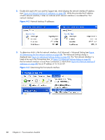
● Use the Nslookup command to determine the IP address that the hostname resolves to. Then, using the arrow buttons to the right of the Connections box on the Advanced Settings screen (see Figure 4-4 Advanced Settings dialog on page 89) change the first network interface to correspond with the IP address returned by Nslookup. After performing this step, you must either reboot the computer, or restart the RGS Sender (see Figure 4-5 Restarting the RGS Sender on page 90). Figure 4-5 Restarting the RGS Sender Network Interface reconfiguration using the Sender network interface binding properties At RGS 5.1, several new Sender properties were added to allow the administrator to configure which network interface(s) the RGS Sender will listen to for connection requests. For a description of these properties, refer to Network Interface binding properties on page 193. Figure 4-6 Network Interface binding order numerical sequence on page 91 shows how the two network interfaces can be referenced in numerical sequence in their binding order. The network interface binding properties permit specification of which network interface (either 0 or 1) the RGS Sender will listen to for connection requests. For example, using the Rgsender.Network.Interface. 1.IsEnabled property, an administrator can specify that the RGS Sender will listen for connection 90 Chapter 4 Pre-connection checklist
-
 1
1 -
2
-
3
-
4
-
5
-
6
-
7
-
8
-
9
-
10
-
11
-
12
-
13
-
14
-
15
-
16
-
17
-
18
-
19
-
20
-
21
-
22
-
23
-
24
-
25
-
26
-
27
-
28
-
29
-
30
-
31
-
32
-
33
-
34
-
35
-
36
-
37
-
38
-
39
-
40
-
41
-
42
-
43
-
44
-
45
-
46
-
47
-
48
-
49
-
50
-
51
-
52
-
53
-
54
-
55
-
56
-
57
-
58
-
59
-
60
-
61
-
62
-
63
-
64
-
65
-
66
-
67
-
68
-
69
-
70
-
71
-
72
-
73
-
74
-
75
-
76
-
77
-
78
-
79
-
80
-
81
-
82
-
83
-
84
-
85
-
86
-
87
-
88
-
89
-
90
-
91
-
92
-
93
-
94
-
95
-
96
-
97
-
98
-
99
-
100
-
 101
101 -
 102
102 -
 103
103 -
 104
104 -
 105
105 -
 106
106 -
 107
107 -
 108
108 -
 109
109 -
 110
110 -
 111
111 -
112
-
113
-
114
-
115
-
116
-
117
-
118
-
119
-
120
-
121
-
122
-
123
-
124
-
125
-
126
-
127
-
128
-
129
-
130
-
131
-
132
-
133
-
134
-
135
-
136
-
137
-
138
-
139
-
140
-
141
-
142
-
143
-
144
-
145
-
146
-
147
-
148
-
149
-
150
-
151
-
152
-
153
-
154
-
155
-
156
-
157
-
158
-
159
-
160
-
161
-
162
-
163
-
164
-
165
-
166
-
167
-
168
-
169
-
170
-
171
-
172
-
173
-
174
-
175
-
176
-
177
-
178
-
179
-
180
-
181
-
182
-
183
-
184
-
185
-
186
-
187
-
188
-
189
-
190
-
191
-
192
-
193
-
194
-
195
-
196
-
197
-
198
-
199
-
200
-
201
-
202
-
203
-
204
-
205
-
206
-
207
-
208
-
209
-
210
-
211
-
212
-
213
-
214
-
215
-
216
-
217
-
218
-
219
-
220
-
221
-
222
-
223
-
224
-
225
-
226
-
227
-
228
-
229
-
230
-
231
-
232
-
233
-
234
-
235
-
236
-
237
-
238
-
239
-
240
-
241
-
242
-
243
-
244
-
245
-
246
-
247
 |
 |
