IBM 6000R Hardware Maintenance Manual - Page 100
Pack Ultra160 Hot-Swap Expansion Kit., SCSI repeater card after the repeater card is installed,
 |
UPC - 087944534341
View all IBM 6000R manuals
Add to My Manuals
Save this manual to your list of manuals |
Page 100 highlights
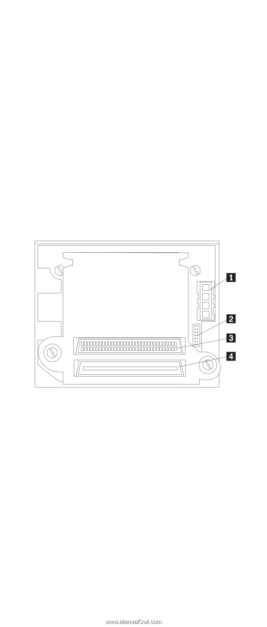
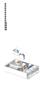
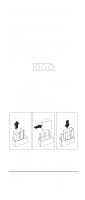
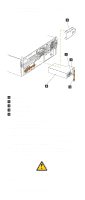
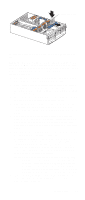
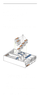
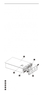
3. For information on cabling options and using the Netfinity 3-Pack Ultra160 Hot-Swap Expansion option, refer to the documentation that comes with the option kit. 4. For additional information on cabling, see "Cabling example for the ServeRAID adapter" on page 71 and "Cabling the server" on page 107. 5. The hot-swap drive backplane components are shown at "Installing a hot-swap hard disk drive" on page 76. Note: The hard-disk drive activity light and hard-disk drive status light on the backplane match the hard-disk drive activity light and hard-disk drive status light on the front of the server (see "Start the server" on page 8). The rear connectors on the hot-swap-drive backplane (before repeater card is installed) can be seen at "Installing a hot-swap hard disk drive" on page 76. The following illustration shows the rear connectors on the SCSI repeater card after the repeater card is installed, as viewed from the rear of the server. 1 SCSI power cable connector 2 I2C cable connector 3 SCSI repeater card cable connector 4 SCSI cable connector The following illustration shows how to install a Netfinity 3Pack Ultra160 Hot-Swap Expansion Kit. 88 Netfinity 6000R Type 8682 Models 1RY, 2RY
-
 1
1 -
2
-
3
-
4
-
5
-
6
-
7
-
8
-
9
-
10
-
11
-
12
-
13
-
14
-
15
-
16
-
17
-
18
-
19
-
20
-
21
-
22
-
23
-
24
-
25
-
26
-
27
-
28
-
29
-
30
-
31
-
32
-
33
-
34
-
35
-
36
-
37
-
38
-
39
-
40
-
41
-
42
-
43
-
44
-
45
-
46
-
47
-
48
-
49
-
50
-
51
-
52
-
53
-
54
-
55
-
56
-
57
-
58
-
59
-
60
-
61
-
62
-
63
-
64
-
65
-
66
-
67
-
68
-
69
-
70
-
71
-
72
-
73
-
74
-
75
-
76
-
77
-
78
-
79
-
80
-
81
-
82
-
83
-
84
-
85
-
86
-
87
-
88
-
89
-
90
-
91
-
92
-
93
-
94
-
 95
95 -
 96
96 -
 97
97 -
 98
98 -
 99
99 -
 100
100 -
 101
101 -
 102
102 -
 103
103 -
 104
104 -
 105
105 -
106
-
107
-
108
-
109
-
110
-
111
-
112
-
113
-
114
-
115
-
116
-
117
-
118
-
119
-
120
-
121
-
122
-
123
-
124
-
125
-
126
-
127
-
128
-
129
-
130
-
131
-
132
-
133
-
134
-
135
-
136
-
137
-
138
-
139
-
140
-
141
-
142
-
143
-
144
-
145
-
146
-
147
-
148
-
149
-
150
-
151
-
152
-
153
-
154
-
155
-
156
-
157
-
158
-
159
-
160
-
161
-
162
-
163
-
164
-
165
-
166
-
167
-
168
-
169
-
170
-
171
-
172
-
173
-
174
-
175
-
176
-
177
-
178
-
179
-
180
-
181
-
182
-
183
-
184
-
185
-
186
-
187
-
188
-
189
-
190
-
191
-
192
-
193
-
194
-
195
-
196
-
197
-
198
-
199
-
200
-
201
-
202
-
203
-
204
-
205
-
206
-
207
-
208
-
209
-
210
-
211
-
212
-
213
-
214
-
215
-
216
-
217
-
218
-
219
-
220
-
221
-
222
-
223
-
224
-
225
-
226
-
227
-
228
-
229
-
230
-
231
-
232
-
233
-
234
-
235
-
236
-
237
-
238
-
239
-
240
-
241
-
242
-
243
-
244
-
245
-
246
-
247
-
248
-
249
-
250
-
251
-
252
 |
 |