IBM 6000R Hardware Maintenance Manual - Page 104
Updating the server configuration, Connecting external options
 |
UPC - 087944534341
View all IBM 6000R manuals
Add to My Manuals
Save this manual to your list of manuals |
Page 104 highlights
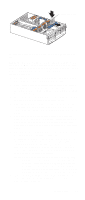
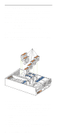
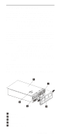
To install the server top cover: 1. Before installing the cover, check that all cables, adapters, and other components are installed and seated correctly and that you have not left loose tools or parts inside the server. 2. Place the cover-release latch in the open (up) position. 3. Insert the bottom tabs of the top cover in the matching slots in the server chassis. 4. Close the cover-release latch to pull the top cover forward and lock the top cover in place. 5. If you disconnected any cables from the back of the server, reconnect the cables; then, plug the power cords into properly grounded electrical outlets. Note: If necessary, refer to "Input/Output ports" on page 93 for connector locations. To install the bezel: 1. Insert the two tabs on the bottom of the bezel into the matching holes on the server chassis. 2. Push the top of the bezel toward the server until the two tabs at the top of the bezel snap into place. Updating the server configuration When you start the server for the first time after you add or remove an internal option or an external SCSI device, you might see a message telling you that the configuration has changed. The Configuration/Setup Utility program automatically starts so that you can save the new configuration information. See "Configuring the server" on page 43. Some options have device drivers that you need to install. Refer to the documentation that comes with your option for information about installing any required device drivers. The server comes with at least one microprocessor installed on the system board. If you have installed one or more additional microprocessors, the server can now operate as an SMP server. Therefore, you might need to upgrade your operating system to support SMP. If the server has a ServeRAID adapter installed and you have installed or removed a hard disk drive, refer to the documentation that comes with your ServeRAID adapter for information about reconfiguring your disk arrays. Connecting external options Before you begin: • Review "Before you begin" on page 63. • Read the documentation that comes with your options. You can attach external options to the input/output (I/O) connectors on the rear of the server. (See "Input/Output ports" on page 93 for more information.) To attach an external device: 92 Netfinity 6000R Type 8682 Models 1RY, 2RY
-
 1
1 -
2
-
3
-
4
-
5
-
6
-
7
-
8
-
9
-
10
-
11
-
12
-
13
-
14
-
15
-
16
-
17
-
18
-
19
-
20
-
21
-
22
-
23
-
24
-
25
-
26
-
27
-
28
-
29
-
30
-
31
-
32
-
33
-
34
-
35
-
36
-
37
-
38
-
39
-
40
-
41
-
42
-
43
-
44
-
45
-
46
-
47
-
48
-
49
-
50
-
51
-
52
-
53
-
54
-
55
-
56
-
57
-
58
-
59
-
60
-
61
-
62
-
63
-
64
-
65
-
66
-
67
-
68
-
69
-
70
-
71
-
72
-
73
-
74
-
75
-
76
-
77
-
78
-
79
-
80
-
81
-
82
-
83
-
84
-
85
-
86
-
87
-
88
-
89
-
90
-
91
-
92
-
93
-
94
-
95
-
96
-
97
-
98
-
 99
99 -
 100
100 -
 101
101 -
 102
102 -
 103
103 -
 104
104 -
 105
105 -
 106
106 -
 107
107 -
 108
108 -
 109
109 -
110
-
111
-
112
-
113
-
114
-
115
-
116
-
117
-
118
-
119
-
120
-
121
-
122
-
123
-
124
-
125
-
126
-
127
-
128
-
129
-
130
-
131
-
132
-
133
-
134
-
135
-
136
-
137
-
138
-
139
-
140
-
141
-
142
-
143
-
144
-
145
-
146
-
147
-
148
-
149
-
150
-
151
-
152
-
153
-
154
-
155
-
156
-
157
-
158
-
159
-
160
-
161
-
162
-
163
-
164
-
165
-
166
-
167
-
168
-
169
-
170
-
171
-
172
-
173
-
174
-
175
-
176
-
177
-
178
-
179
-
180
-
181
-
182
-
183
-
184
-
185
-
186
-
187
-
188
-
189
-
190
-
191
-
192
-
193
-
194
-
195
-
196
-
197
-
198
-
199
-
200
-
201
-
202
-
203
-
204
-
205
-
206
-
207
-
208
-
209
-
210
-
211
-
212
-
213
-
214
-
215
-
216
-
217
-
218
-
219
-
220
-
221
-
222
-
223
-
224
-
225
-
226
-
227
-
228
-
229
-
230
-
231
-
232
-
233
-
234
-
235
-
236
-
237
-
238
-
239
-
240
-
241
-
242
-
243
-
244
-
245
-
246
-
247
-
248
-
249
-
250
-
251
-
252
 |
 |