IBM 6000R Hardware Maintenance Manual - Page 93
Installing a microprocessor kit, Bulletin Board System BBS.
 |
UPC - 087944534341
View all IBM 6000R manuals
Add to My Manuals
Save this manual to your list of manuals |
Page 93 highlights
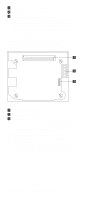
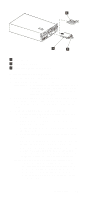
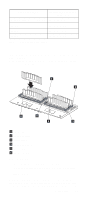
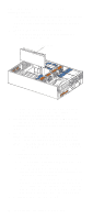
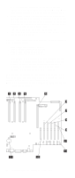
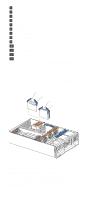
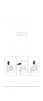
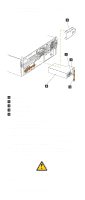
a. Hold the memory board assembly, and align it into the card guides and over the memory board connector. Attention: When you insert the memory board assembly into the connector, press on the flat metal projection on the board. b. Insert the memory board assembly into the connector. 7. If you have other options to install or remove, do so now; otherwise, go to "Installing the server top cover and bezel" on page 91. Installing a microprocessor kit The server comes with one microprocessor installed on the system board. The server supports up to four microprocessors. If you install at least one additional microprocessor, the server can operate as a symmetric multiprocessing (SMP) server. With SMP, certain operating systems and application programs can distribute the processing load among the microprocessors. Before you begin: • Review the information in "Before you begin" on page 63. • Thoroughly review the documentation that comes with the microprocessor, so that you can determine whether you need to update the server basic input/output system (BIOS). The latest level of BIOS for the server is available through the World Wide Web and the IBM Bulletin Board System (BBS). Go to http://www.pc.ibm.com/support/, select IBM Servers, and make the selections for the server. • Obtain an SMP-capable operating system (optional). For a list of supported operating systems, see http://www.ibm.com/pc/us/compat/ on the World Wide Web. Attention: To avoid damage and ensure proper server operation when you install a new or an additional microprocessor, use microprocessors that have the same cache size and type, and the same clock speed. Microprocessor internal and external clock frequencies must be identical. Notes: 1. To order additional microprocessor options, contact your IBM reseller or IBM marketing representative. 2. The server comes standard with one microprocessor installed in microprocessor connector J34 (slot 1) on the system board, and a terminator card in microprocessor slot 4. The microprocessor in slot 1 is the startup (boot) microprocessor. The microprocessor installed in microprocessor connector J35 is microprocessor 2 (slot 2); the microprocessor installed in microprocessor connector J36 is microprocessor 3 (slot 3); and the microprocessor installed in microprocessor connector J37 is microprocessor 4 (slot 4). If more than one microprocessor is installed, the highest num- Installing options 81
-
 1
1 -
2
-
3
-
4
-
5
-
6
-
7
-
8
-
9
-
10
-
11
-
12
-
13
-
14
-
15
-
16
-
17
-
18
-
19
-
20
-
21
-
22
-
23
-
24
-
25
-
26
-
27
-
28
-
29
-
30
-
31
-
32
-
33
-
34
-
35
-
36
-
37
-
38
-
39
-
40
-
41
-
42
-
43
-
44
-
45
-
46
-
47
-
48
-
49
-
50
-
51
-
52
-
53
-
54
-
55
-
56
-
57
-
58
-
59
-
60
-
61
-
62
-
63
-
64
-
65
-
66
-
67
-
68
-
69
-
70
-
71
-
72
-
73
-
74
-
75
-
76
-
77
-
78
-
79
-
80
-
81
-
82
-
83
-
84
-
85
-
86
-
87
-
 88
88 -
 89
89 -
 90
90 -
 91
91 -
 92
92 -
 93
93 -
 94
94 -
 95
95 -
 96
96 -
 97
97 -
 98
98 -
99
-
100
-
101
-
102
-
103
-
104
-
105
-
106
-
107
-
108
-
109
-
110
-
111
-
112
-
113
-
114
-
115
-
116
-
117
-
118
-
119
-
120
-
121
-
122
-
123
-
124
-
125
-
126
-
127
-
128
-
129
-
130
-
131
-
132
-
133
-
134
-
135
-
136
-
137
-
138
-
139
-
140
-
141
-
142
-
143
-
144
-
145
-
146
-
147
-
148
-
149
-
150
-
151
-
152
-
153
-
154
-
155
-
156
-
157
-
158
-
159
-
160
-
161
-
162
-
163
-
164
-
165
-
166
-
167
-
168
-
169
-
170
-
171
-
172
-
173
-
174
-
175
-
176
-
177
-
178
-
179
-
180
-
181
-
182
-
183
-
184
-
185
-
186
-
187
-
188
-
189
-
190
-
191
-
192
-
193
-
194
-
195
-
196
-
197
-
198
-
199
-
200
-
201
-
202
-
203
-
204
-
205
-
206
-
207
-
208
-
209
-
210
-
211
-
212
-
213
-
214
-
215
-
216
-
217
-
218
-
219
-
220
-
221
-
222
-
223
-
224
-
225
-
226
-
227
-
228
-
229
-
230
-
231
-
232
-
233
-
234
-
235
-
236
-
237
-
238
-
239
-
240
-
241
-
242
-
243
-
244
-
245
-
246
-
247
-
248
-
249
-
250
-
251
-
252
 |
 |