IBM 6000R Hardware Maintenance Manual - Page 83
Cabling example for the ServeRAID adapter, firmly, Using IBM ServeRAID
 |
UPC - 087944534341
View all IBM 6000R manuals
Add to My Manuals
Save this manual to your list of manuals |
Page 83 highlights
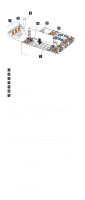
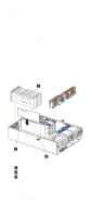
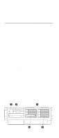
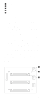
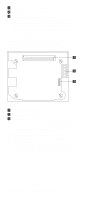
c. Press on the rear of the adapter retention assembly and lift the adapter retention cover. Attention: Expansion-slot covers must be installed on all empty slots. This maintains the electromagnetic emissions characteristics of the system and ensures proper cooling of system components. 5. Refer to the documentation that comes with your adapter for any cabling instructions. It might be easier for you to route any cables before you install the adapter. 6. Remove the adapter from the static-protective package. Attention: Avoid touching the components and goldedge connectors on the adapter. 7. Place the adapter, component-side up, on a flat, staticprotective surface. 8. Install the adapter: a. Carefully grasp the adapter by its top edge or upper corners, and align it with the expansion slot on the system board. b. Press the adapter firmly into the expansion slot. Attention: When you install an adapter in the server, be sure that it is completely and correctly seated in the system-board connector. Incomplete insertion might cause damage to the system board or the adapter. c. Lower the tab over the top corner of the adapter. Rotate the adapter retention latch clockwise until it snaps into place. 9. Connect any needed cables to the adapter. 10. Enable the PCI slot from your operating system. (Refer to the documentation that comes with your operating system for information about enabling a hot-plug PCI slot.) Make sure that the power-on light for the hot-plug PCI slot comes on. 11. If you have other options to install or remove, do so now; otherwise, go to "Installing the server top cover and bezel" on page 91. Cabling example for the ServeRAID adapter You can install an optional IBM ServeRAID® adapter in the server to control the internal hot-swap hard-disk drives; that is, to enable you to configure the internal hot-swap hard disk drives into disk arrays. To do this, you must turn off the server, disconnect the internal SCSI cable from the integrated SCSI controller on the system board, and connect the cable to a ServeRAID adapter. Refer to the ServeRAID adapter option documentation for complete instructions on installing a ServeRAID adapter in the server. Refer to the Using IBM ServeRAID book on the Documentation CD for information on ServeRAID adapters and controllers. The following procedure describes the cable routing that is necessary when you install a ServeRAID adapter. The following illustrations show the cabling for internal hot-swap Installing options 71
-
 1
1 -
2
-
3
-
4
-
5
-
6
-
7
-
8
-
9
-
10
-
11
-
12
-
13
-
14
-
15
-
16
-
17
-
18
-
19
-
20
-
21
-
22
-
23
-
24
-
25
-
26
-
27
-
28
-
29
-
30
-
31
-
32
-
33
-
34
-
35
-
36
-
37
-
38
-
39
-
40
-
41
-
42
-
43
-
44
-
45
-
46
-
47
-
48
-
49
-
50
-
51
-
52
-
53
-
54
-
55
-
56
-
57
-
58
-
59
-
60
-
61
-
62
-
63
-
64
-
65
-
66
-
67
-
68
-
69
-
70
-
71
-
72
-
73
-
74
-
75
-
76
-
77
-
 78
78 -
 79
79 -
 80
80 -
 81
81 -
 82
82 -
 83
83 -
 84
84 -
 85
85 -
 86
86 -
 87
87 -
 88
88 -
89
-
90
-
91
-
92
-
93
-
94
-
95
-
96
-
97
-
98
-
99
-
100
-
101
-
102
-
103
-
104
-
105
-
106
-
107
-
108
-
109
-
110
-
111
-
112
-
113
-
114
-
115
-
116
-
117
-
118
-
119
-
120
-
121
-
122
-
123
-
124
-
125
-
126
-
127
-
128
-
129
-
130
-
131
-
132
-
133
-
134
-
135
-
136
-
137
-
138
-
139
-
140
-
141
-
142
-
143
-
144
-
145
-
146
-
147
-
148
-
149
-
150
-
151
-
152
-
153
-
154
-
155
-
156
-
157
-
158
-
159
-
160
-
161
-
162
-
163
-
164
-
165
-
166
-
167
-
168
-
169
-
170
-
171
-
172
-
173
-
174
-
175
-
176
-
177
-
178
-
179
-
180
-
181
-
182
-
183
-
184
-
185
-
186
-
187
-
188
-
189
-
190
-
191
-
192
-
193
-
194
-
195
-
196
-
197
-
198
-
199
-
200
-
201
-
202
-
203
-
204
-
205
-
206
-
207
-
208
-
209
-
210
-
211
-
212
-
213
-
214
-
215
-
216
-
217
-
218
-
219
-
220
-
221
-
222
-
223
-
224
-
225
-
226
-
227
-
228
-
229
-
230
-
231
-
232
-
233
-
234
-
235
-
236
-
237
-
238
-
239
-
240
-
241
-
242
-
243
-
244
-
245
-
246
-
247
-
248
-
249
-
250
-
251
-
252
 |
 |