IBM 6000R Hardware Maintenance Manual - Page 162
Power backplane assembly, Remove the system board assembly see System
 |
UPC - 087944534341
View all IBM 6000R manuals
Add to My Manuals
Save this manual to your list of manuals |
Page 162 highlights
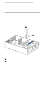
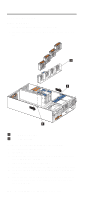
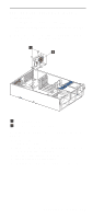
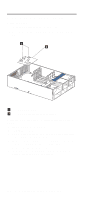
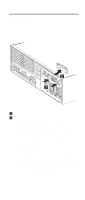
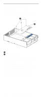
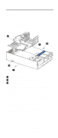
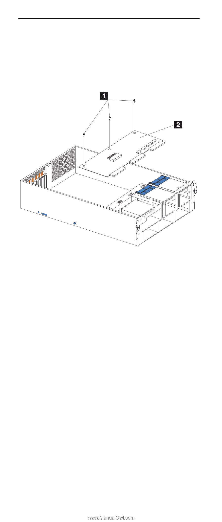
Power backplane assembly Before you begin: • Read "Safety information" on page 196. • Review the information in "Before you begin" on page 63. 1 Holding screws 2 Power backplane To remove the power backplane assembly, do the following: 1. Power-off the server, if it is on. 2. Unplug the server. 3. Remove the top cover (see "Removing the server top cover and bezel" on page 67). 4. Remove the system board assembly (see "System board assembly with backerplate" on page 151). 5. Disconnect all cables to the power backplane. 6. Remove the three holding screws. 7. Lift the power backplane out of the server. 150 Netfinity 6000R Type 8682 Models 1RY, 2RY
-
 1
1 -
2
-
3
-
4
-
5
-
6
-
7
-
8
-
9
-
10
-
11
-
12
-
13
-
14
-
15
-
16
-
17
-
18
-
19
-
20
-
21
-
22
-
23
-
24
-
25
-
26
-
27
-
28
-
29
-
30
-
31
-
32
-
33
-
34
-
35
-
36
-
37
-
38
-
39
-
40
-
41
-
42
-
43
-
44
-
45
-
46
-
47
-
48
-
49
-
50
-
51
-
52
-
53
-
54
-
55
-
56
-
57
-
58
-
59
-
60
-
61
-
62
-
63
-
64
-
65
-
66
-
67
-
68
-
69
-
70
-
71
-
72
-
73
-
74
-
75
-
76
-
77
-
78
-
79
-
80
-
81
-
82
-
83
-
84
-
85
-
86
-
87
-
88
-
89
-
90
-
91
-
92
-
93
-
94
-
95
-
96
-
97
-
98
-
99
-
100
-
101
-
102
-
103
-
104
-
105
-
106
-
107
-
108
-
109
-
110
-
111
-
112
-
113
-
114
-
115
-
116
-
117
-
118
-
119
-
120
-
121
-
122
-
123
-
124
-
125
-
126
-
127
-
128
-
129
-
130
-
131
-
132
-
133
-
134
-
135
-
136
-
137
-
138
-
139
-
140
-
141
-
142
-
143
-
144
-
145
-
146
-
147
-
148
-
149
-
150
-
151
-
152
-
153
-
154
-
155
-
156
-
 157
157 -
 158
158 -
 159
159 -
 160
160 -
 161
161 -
 162
162 -
 163
163 -
 164
164 -
 165
165 -
 166
166 -
 167
167 -
168
-
169
-
170
-
171
-
172
-
173
-
174
-
175
-
176
-
177
-
178
-
179
-
180
-
181
-
182
-
183
-
184
-
185
-
186
-
187
-
188
-
189
-
190
-
191
-
192
-
193
-
194
-
195
-
196
-
197
-
198
-
199
-
200
-
201
-
202
-
203
-
204
-
205
-
206
-
207
-
208
-
209
-
210
-
211
-
212
-
213
-
214
-
215
-
216
-
217
-
218
-
219
-
220
-
221
-
222
-
223
-
224
-
225
-
226
-
227
-
228
-
229
-
230
-
231
-
232
-
233
-
234
-
235
-
236
-
237
-
238
-
239
-
240
-
241
-
242
-
243
-
244
-
245
-
246
-
247
-
248
-
249
-
250
-
251
-
252
 |
 |
150
Netfinity 6000R Type 8682 Models 1RY, 2RY
Power backplane assembly
Before you begin:
•
Read “Safety information” on page 196.
•
Review the information in “Before you begin” on page
63.
±
1
²
Holding screws
±
2
²
Power backplane
To remove the power backplane assembly, do the following:
1.
Power-off the server, if it is on.
2.
Unplug the server.
3.
Remove the top cover (see “Removing the server top
cover and bezel” on page 67).
4.
Remove the system board assembly (see “System
board assembly with backerplate” on page 151).
5.
Disconnect all cables to the power backplane.
6.
Remove the three holding screws.
7.
Lift the power backplane out of the server.