IBM 6000R Hardware Maintenance Manual - Page 38
Refer to Using, Tilt the battery so that you can insert it into
 |
UPC - 087944534341
View all IBM 6000R manuals
Add to My Manuals
Save this manual to your list of manuals |
Page 38 highlights
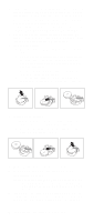
3. Turn off the server and all attached devices and disconnect all external cables and power cords (see "Safety information" on page 196); then remove the top cover. 4. Locate the battery on the system board (see "System board component locations" on page 54). 5. Remove adapters as necessary so you can access the battery. (See "Working with adapters" on page 68.) 6. Lift and remove the plastic dividers by pressing the latches on the top ends of the dividers toward the dividers and lifting the dividers from the server. 7. Remove the battery: a. Use one finger to lift the battery clip over the battery. b. Use one finger to slightly slide the battery toward the rear of the server. The spring mechanism behind the battery will push it out toward you as you slide it forward. c. Use your thumb and index finger to pull the battery from under the battery clip. d. Ensure that the battery clip is touching the base of the battery socket by pressing gently on the clip. 8. Insert the new battery: a. Tilt the battery so that you can insert it into the front of the socket, under the battery clip. b. As you slide it under the battery clip, press the battery down into the socket. 9. Reinstall any adapters that you removed. 10. Insert the plastic dividers into the divider guides. 11. Reinstall the top cover. Note: You must wait approximately 20 seconds after you plug the power cord of the server into an electrical outlet before the power control button becomes active. 12. Start the Configuration/Setup Utility program and set configuration parameters as needed. Refer to "Using the Configuration/Setup Utility program" on page 43. 26 Netfinity 6000R Type 8682 Models 1RY, 2RY
-
 1
1 -
2
-
3
-
4
-
5
-
6
-
7
-
8
-
9
-
10
-
11
-
12
-
13
-
14
-
15
-
16
-
17
-
18
-
19
-
20
-
21
-
22
-
23
-
24
-
25
-
26
-
27
-
28
-
29
-
30
-
31
-
32
-
 33
33 -
 34
34 -
 35
35 -
 36
36 -
 37
37 -
 38
38 -
 39
39 -
 40
40 -
 41
41 -
 42
42 -
 43
43 -
44
-
45
-
46
-
47
-
48
-
49
-
50
-
51
-
52
-
53
-
54
-
55
-
56
-
57
-
58
-
59
-
60
-
61
-
62
-
63
-
64
-
65
-
66
-
67
-
68
-
69
-
70
-
71
-
72
-
73
-
74
-
75
-
76
-
77
-
78
-
79
-
80
-
81
-
82
-
83
-
84
-
85
-
86
-
87
-
88
-
89
-
90
-
91
-
92
-
93
-
94
-
95
-
96
-
97
-
98
-
99
-
100
-
101
-
102
-
103
-
104
-
105
-
106
-
107
-
108
-
109
-
110
-
111
-
112
-
113
-
114
-
115
-
116
-
117
-
118
-
119
-
120
-
121
-
122
-
123
-
124
-
125
-
126
-
127
-
128
-
129
-
130
-
131
-
132
-
133
-
134
-
135
-
136
-
137
-
138
-
139
-
140
-
141
-
142
-
143
-
144
-
145
-
146
-
147
-
148
-
149
-
150
-
151
-
152
-
153
-
154
-
155
-
156
-
157
-
158
-
159
-
160
-
161
-
162
-
163
-
164
-
165
-
166
-
167
-
168
-
169
-
170
-
171
-
172
-
173
-
174
-
175
-
176
-
177
-
178
-
179
-
180
-
181
-
182
-
183
-
184
-
185
-
186
-
187
-
188
-
189
-
190
-
191
-
192
-
193
-
194
-
195
-
196
-
197
-
198
-
199
-
200
-
201
-
202
-
203
-
204
-
205
-
206
-
207
-
208
-
209
-
210
-
211
-
212
-
213
-
214
-
215
-
216
-
217
-
218
-
219
-
220
-
221
-
222
-
223
-
224
-
225
-
226
-
227
-
228
-
229
-
230
-
231
-
232
-
233
-
234
-
235
-
236
-
237
-
238
-
239
-
240
-
241
-
242
-
243
-
244
-
245
-
246
-
247
-
248
-
249
-
250
-
251
-
252
 |
 |
