IBM 6000R Hardware Maintenance Manual - Page 96
Hunpainted LTable 12. LMicroprocessor-core-frequency-selection jumper Hblock settings, Attention
 |
UPC - 087944534341
View all IBM 6000R manuals
Add to My Manuals
Save this manual to your list of manuals |
Page 96 highlights
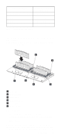
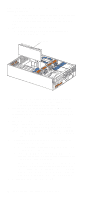
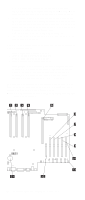
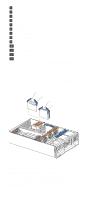
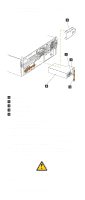
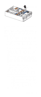
Note: If you are replacing a failed microprocessor, verify that you have selected the correct microprocessor for replacement. To do this, check the Diagnostic panel that is located under the top cover to see which LED is on. 1. Turn off the server and disconnect all power cords and external cables; then, remove the top cover (see "Removing the server top cover and bezel" on page 67). 2. Determine the slot where the microprocessor is to be installed. 3. If you have installed microprocessors in slots 1 through 3 and you are now installing a microprocessor in slot 4, remove the terminator card from the microprocessor connector. Store the terminator card in a safe place in the static-protective package that your new microprocessor comes in; you will need to install it again if you ever remove the microprocessor. 4. Install the microprocessor: a. Touch the static-protective package containing the new microprocessor to any unpainted metal surface on the server; then, remove the microprocessor from the package. b. Hold the microprocessor by the open latches, and center the microprocessor over the microprocessor connector. Attention: Make sure that the microprocessor is oriented and aligned correctly before you try to close the latches. c. Carefully close the latches to seat the microprocessor in the connector. 5. If you replace the microprocessors in the server with microprocessors of a different speed, set the microprocessor-core-frequency-selection jumper block as described in Table 12. To ensure that the server maintains the correct microprocessor bus-to-core ratio, you must set the following microprocessor speed (core-frequency-selection) jumpers: J13, J27, J28, and J29. The jumpers on this block are in the following order, from top to bottom: J13, J27, J28, and J29. For locations of these jumpers, see "System board jumpers" on page 56. Note: See "Changing jumper positions" on page 85 for additional information on setting jumpers. J13 J27 J28 J29 Bus Ratio Core Frequency (MHz) H L L H 7:1 700/100 Table 12. Microprocessor-core-frequency-selection jumper block settings 6. If you have other options to install or remove, do so now; otherwise, go to "Installing the server top cover and bezel" on page 91. 84 Netfinity 6000R Type 8682 Models 1RY, 2RY
-
 1
1 -
2
-
3
-
4
-
5
-
6
-
7
-
8
-
9
-
10
-
11
-
12
-
13
-
14
-
15
-
16
-
17
-
18
-
19
-
20
-
21
-
22
-
23
-
24
-
25
-
26
-
27
-
28
-
29
-
30
-
31
-
32
-
33
-
34
-
35
-
36
-
37
-
38
-
39
-
40
-
41
-
42
-
43
-
44
-
45
-
46
-
47
-
48
-
49
-
50
-
51
-
52
-
53
-
54
-
55
-
56
-
57
-
58
-
59
-
60
-
61
-
62
-
63
-
64
-
65
-
66
-
67
-
68
-
69
-
70
-
71
-
72
-
73
-
74
-
75
-
76
-
77
-
78
-
79
-
80
-
81
-
82
-
83
-
84
-
85
-
86
-
87
-
88
-
89
-
90
-
 91
91 -
 92
92 -
 93
93 -
 94
94 -
 95
95 -
 96
96 -
 97
97 -
 98
98 -
 99
99 -
 100
100 -
 101
101 -
102
-
103
-
104
-
105
-
106
-
107
-
108
-
109
-
110
-
111
-
112
-
113
-
114
-
115
-
116
-
117
-
118
-
119
-
120
-
121
-
122
-
123
-
124
-
125
-
126
-
127
-
128
-
129
-
130
-
131
-
132
-
133
-
134
-
135
-
136
-
137
-
138
-
139
-
140
-
141
-
142
-
143
-
144
-
145
-
146
-
147
-
148
-
149
-
150
-
151
-
152
-
153
-
154
-
155
-
156
-
157
-
158
-
159
-
160
-
161
-
162
-
163
-
164
-
165
-
166
-
167
-
168
-
169
-
170
-
171
-
172
-
173
-
174
-
175
-
176
-
177
-
178
-
179
-
180
-
181
-
182
-
183
-
184
-
185
-
186
-
187
-
188
-
189
-
190
-
191
-
192
-
193
-
194
-
195
-
196
-
197
-
198
-
199
-
200
-
201
-
202
-
203
-
204
-
205
-
206
-
207
-
208
-
209
-
210
-
211
-
212
-
213
-
214
-
215
-
216
-
217
-
218
-
219
-
220
-
221
-
222
-
223
-
224
-
225
-
226
-
227
-
228
-
229
-
230
-
231
-
232
-
233
-
234
-
235
-
236
-
237
-
238
-
239
-
240
-
241
-
242
-
243
-
244
-
245
-
246
-
247
-
248
-
249
-
250
-
251
-
252
 |
 |